Kramer Electronics VP-1201 User Manual
Page 8
KRAMER: SIMPLE CREATIVE TECHNOLOGY
Your VP-1201 12x1 XGA Switcher / Scanner
4
Table 1: Front Panel
VP-1201 12x1 XGA Switcher / Scanner Features
#
Feature
Function
1 IR Receiver
The red LED is illuminated when receiving signals from the
Kramer Infra-Red remote control transmitter
2
POWER
Switch
Illuminated switch supplying power to the unit
3
INPUT SELECTOR
Buttons
1
Select the input to switch to the output (from 1 to 12):
The blue LED illuminates when a signal is detected on the input
The red LED illuminates when the input is routed to the output
but no signal is detected on the input
Both the blue and red LEDs illuminate (creating purple) when a
signal is transmitted to the output
Table 2: Rear Panel VP-1201 12x1 XGA Switcher / Scanner Features
#
Feature
Function
4
HD15
F Input Connectors
Connect to the video sources (
IN1 through IN12
)
5
HD15
F
BUS
Connector
Bus connector for cascading VP-1201 units
6
HD15
F
BUS LOOP
Connector
Loop for bus connector
7
BUS TERM
Button
Press for BUS termination
8
HD15
F
OUTPUT
Connector
Connects to the output acceptor
9 Setup Dipswitches
For machine setup (see section 5.7)
10
ETHERNET
Connector
Connects to the PC or other controller through computer
networking
11
RS-232 DB 9F
Connector
Connects to the PC or other Serial Controller
12
RS-485
Connector
Used for bi-directional communication with another unit
13 Power Connector with
Fuse
AC connector enabling power supply to the unit
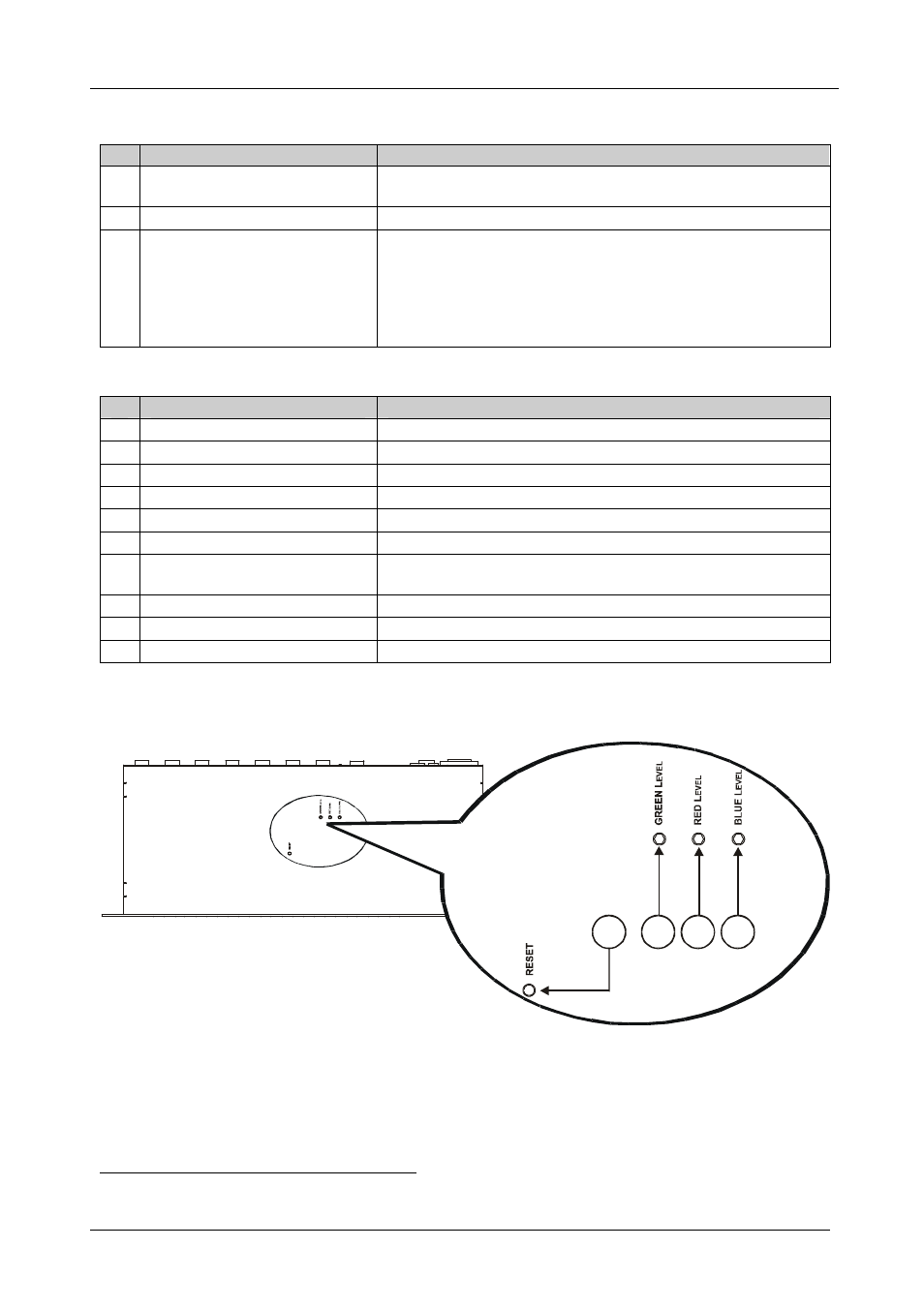
Figure 2 illustrates the underside of the
VP-1201 unit and Table 3 defines the
underside features.
Enlarged View
4
3
2
1
Figure 2: VP-1201 Underside Panel
1 The INPUT SELECTOR buttons are also used to set the highest machine number (see section 5.5.2)