When a single unit is connected) and the rc-3000 – Kramer Electronics VP-1201 User Manual
Page 12
KRAMER: SIMPLE CREATIVE TECHNOLOGY
Connecting a VP-1201 12x1 XGA Switcher / Scanner
8
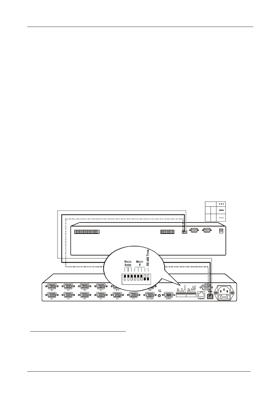
5.3 Controlling via RS-485
You can control a
VP-1201 unit via an RS-485 controller
1
, for example, a PC
(equipped with an RS-485 interface) or a Master Programmable Remote
Control system, such as the Kramer
RC-3000
2
.
To connect an
RC-3000 to a single VP-1201 unit (see Figure 5):
1. Connect the RS-485 terminal block port on the
RC-3000 to the RS-485
port on the
VP-1201 unit, as follows:
Connect the “A” (+) PIN on the RS-485 rear panel port of the
RC-3000
to the “A” (+) PIN on the RS-485 rear panel port of the
VP-1201 unit
Connect the “B” (-) PIN on the RS-485 rear panel port of the
RC-3000
to the “B” (-) PIN on the RS-485 rear panel port of the
VP-1201 unit
If shielded twisted pair cable is used, the shield may be connected to the
“G” (Ground) PIN on one of the units (for example, on the
RC-3000)
2. Set the MACH. # dipswitches on the
VP-1201 unit to Machine # 2 (or
any other number other than 1), according to Table 10.
Do not set as Machine # 1 (the Master).
3. Terminate the RS-485 line on both the
VP-1201 unit
3
(when a single
unit is connected) and the
RC-3000
4
.
KEYBOARD EXTENSION
REMOTE CONTACT
RS-485
RS-232 IN
RS-232 OUT
12 VDC
1 2
1 2 3 4 5 6 7 8 G
4
6
8
10
3
5
7
9
11 12
14
16
OU
T
13
15
IN
RS-485 PINOUT
G
B
A
_
+
1
ON
OFF
2 3 4 5 6
7 8
Figure 5: Controlling via RS-485 (for example, using an RC-3000)
1 RS-485 can be used for control even for distances exceeding 1km
2
Previously known as the VS-3000
3
To terminate RS-485 line on the VP-1201, set dipswitch 8 to ON (see section 5.7)
4 Refer to the RC-3000 user manual for details of how to terminate the RS-485 line