Kramer Electronics VP-1201 User Manual
Page 36
KRAMER: SIMPLE CREATIVE TECHNOLOGY
Operating the VP-1201
32
6.2 The VP-1201 Input Buttons
The Input buttons on the front panel give the following indications:
The blue LED illuminates when a valid input is connected
The red LED illuminates when an input is routed to the output but no
valid signal is detected on the input
Both the blue and red LEDs illuminate (creating purple) when a valid
input signal is being routed to the output
To understand how the Input button LEDs function, consider the following
example:
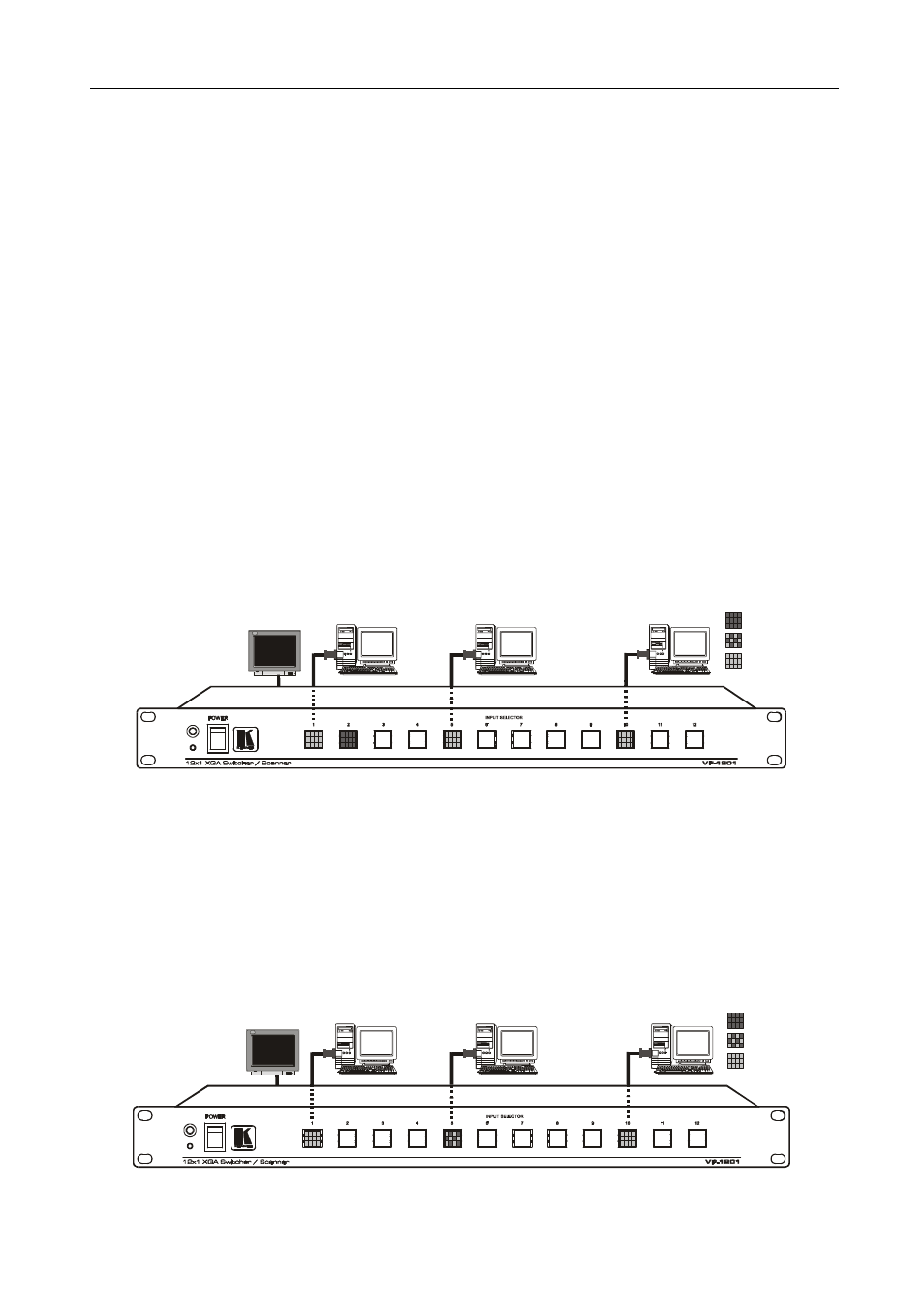
Figure 28 shows an acceptor connected to the
VP-1201 unit and 3 sources
connected to inputs # 1, 5 and 10.
On the front panel we can see that:
The blue LEDs in buttons 1, 5 and 10 are illuminated (indicating that
these 3 sources are connected and active)
The red LED in button 2 is illuminated (indicating that Input 2 is routed to
the output – but there is no active source connected to Input 2)
= Red
= Purple
= Blue
Display
Input 1
Input 5
Input 10
Figure 28: VP-1201 Input Buttons Illuminated (I)
We now want to route Input 5 to the output (see Figure 29). To do so we have
to press the Input 5 button. On the front panel we can see that:
The blue LEDS are illuminated in Input buttons 1, and 10
The red and blue LEDs in button 5 are also illuminated (creating purple)
because input 5 is now routed to the output
The Input 2 button no longer illuminates
= Red
= Purple
= Blue
Display
Input 1
Input 5
Input 10
Figure 29: VP-1201 Input Buttons Illuminated (II)