Connecting the breakout panel, Connecting the e1 patch panel, Figure 2-2. the breakout panel -5 – ADTRAN MX2800 M13 User Manual
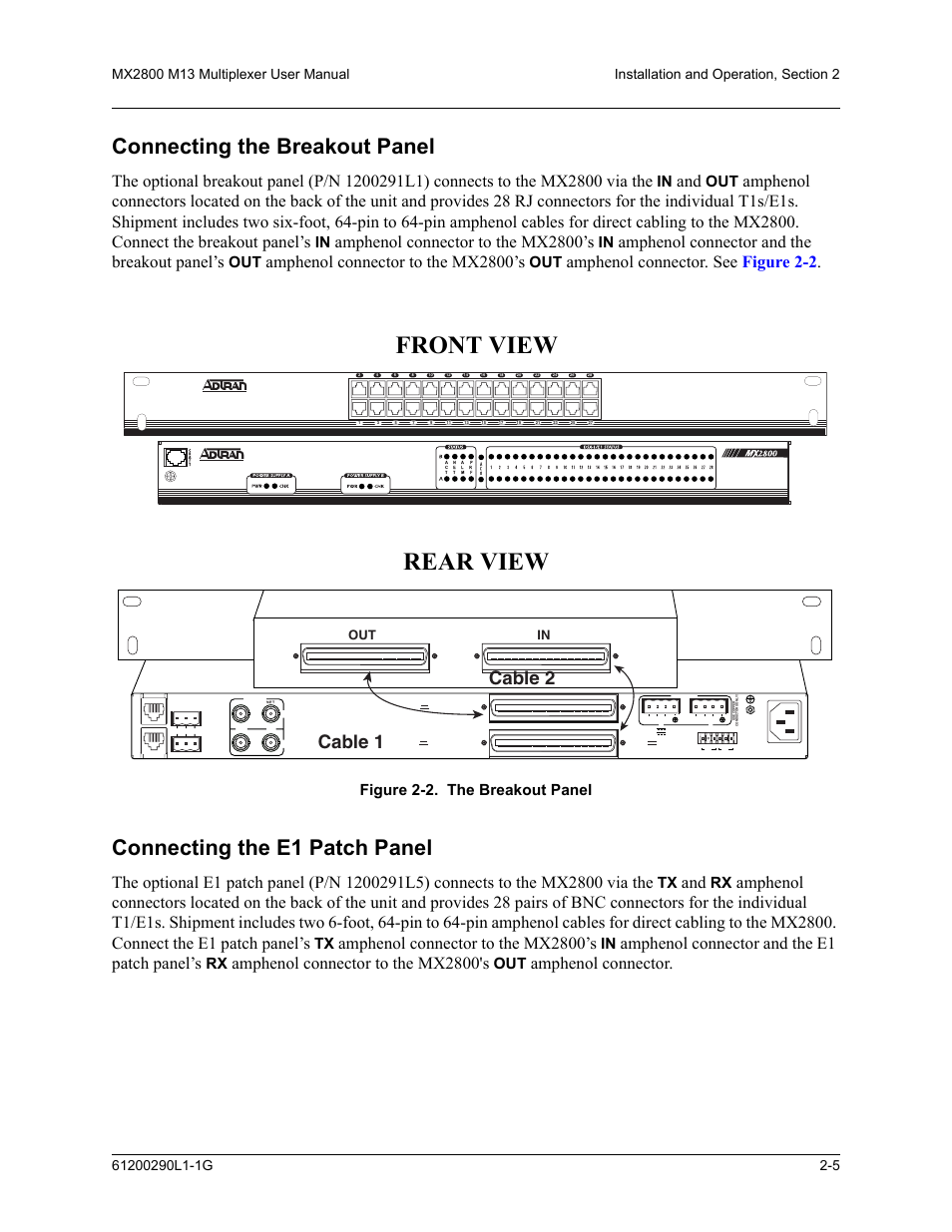
Page 27: Front view rear view, Cable 2 cable 1, Amphenol connector to the mx2800’s, Amphenol connector and the breakout panel’s, Amphenol connector. see figure 2-2, Amphenol connector and the e1 patch panel’s, Amphenol connector to the mx2800's
 Connecting the breakout panel, Connecting the e1 patch panel, Figure 2-2. the breakout panel -5 | Front view rear view, Cable 2 cable 1, Amphenol connector to the mx2800’s, Amphenol connector and the breakout panel’s, Amphenol connector. see figure 2-2, Amphenol connector and the e1 patch panel’s, Amphenol connector to the mx2800's | ADTRAN MX2800 M13 User Manual | Page 27 / 200
 See also other documents in the category ADTRAN Hardware:
- Express 4110 (205 pages)
- Gigabit Ethernet Multi-Mode Fiber Tributary Module 1184519L1 (2 pages)
- U-BR1TE ISDN 2B1Q (4 pages)
- DSU/CSU (6 pages)
- 3010 (30 pages)
- NetVanta 1024 (2 pages)
- FT1 (10 pages)
- IP Mini-DSLAM (2 pages)
- 6530 (20 pages)
- 6530 (2 pages)
- AHT1U (2 pages)
- DS3 MX (2 pages)
- 600R (264 pages)
- DUAL Nx56/64 1200142L1# (42 pages)
- NetVanta T1/FT1 + DSX-1 (2 pages)
- IQ SERIES 56 (1 page)
- 1200070L2 (187 pages)
- 1200051L2 (165 pages)
- NETVANTA 3120 (2 pages)
- 1200 (2 pages)
- NetVanta Series (2 pages)
- 850 (4 pages)
- ATLAS 800 Series Module QUAD E1 (2 pages)
- Atlas 830 (2 pages)
- TSU LT (2 pages)
- Express L1.5 (2 pages)
- MX2820-48 VDC M13 MUX (2 pages)
- Dial Backup Interface Module 1204006L2 (2 pages)
- 900 Series (2 pages)
- Atlas 550 (262 pages)
- Atlas 550 (1 page)
- NetVanta 5305 (2 pages)
- 1200350L1 (134 pages)
- ATM Mini-DSLAM (2 pages)
- D4-n x 64 DSU DP (4 pages)
- Type 400 (4 pages)
- 1204002L1 (163 pages)
- NetVanta ADSL (2 pages)
- 3000 HTU-C (2 pages)
- 600e (2 pages)
- 1200F (2 pages)
- D4 TRI-C DP (1 page)
- 239 T1 HDSL4 (20 pages)
- 3000 NTU-8 (18 pages)
- 1200130L1 (153 pages)