Bell & Gossett P5002169C Series VSCS User Manual
Page 9
7
BASE PLATE SETTING
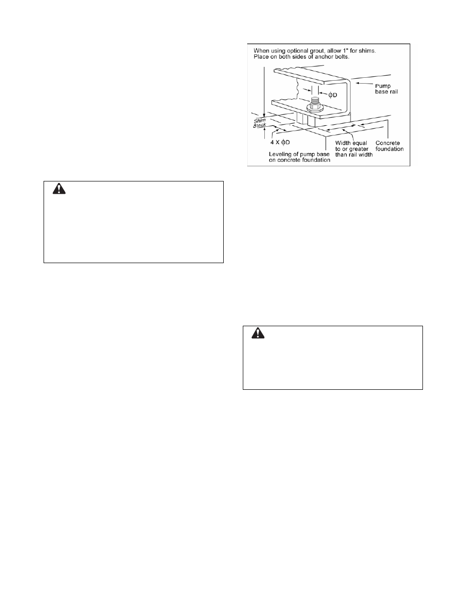
Place the pump unit on its concrete foundation,
supporting it with steel wedges or shims. The
wedges or shims should be machined and be put
on both sides of each anchor bolt to provide a
means for leveling the base. The wedge or shim
width should be equal to or greater than the base
rail width. The length of the wedge or shim should
be at least four times the diameter of the anchor
bolt. It is acceptable to place additional shims
between the existing anchor bolts.
Use an anchor bolt for each anchor bolt hole
provided, and plain, flat Type-W washers at each
anchor bolt.
CAUTION: Equipment Damage
Use an anchor bolt and plain, flat Type-W washer
at each anchor bolt hole. Otherwise, shifting of the
pump unit may occur.
Failure to follow these instructions could result in
serious property damage and/or moderate
personal injury.
It is very important that the pump base be set level
to avoid any mechanical difficulties with the motor
or pump. This pump was properly aligned (if
furnished with a motor) at the factory. However,
since all pump bases are flexible, they may spring
and twist during shipment. Do not pipe the pump
until it is realigned. After piping is completed and
after the pump is installed and bolted down, align it
again. It may be necessary to re-adjust the
alignment from time to time while the unit and
foundation are new.
Optional Grouting
It is permissible to grout the base after the
pump unit has been leveled, securely bolted
to the floor, and properly aligned. A good
grade of non-shrinking grout should be used
inside the pump base.
Figure 7: Setting Base Plate
ROTATION
The Series VSX pump is available in both right-
and left-hand rotation. An arrow cast into the pump
body shows the direction of rotation.
COUPLING ALIGNMENT
All alignment should be done by moving or
shimming the motor only. Adjustments in one
direction may alter alignment in another.
Therefore, check alignment in all directions after a
correction is made. All measurements should be
taken with the pump and motor bolts tightened.
Final alignment check should be made after the
unit has attained its final operating temperature.
WARNING: Unexpected Startup Hazard
Disconnect and lockout power before servicing.
Failure to follow these instructions could result in
serious personal injury or death, or property
damage.
1. Check the pump and motor shafts and
remove any paint, burrs, rust, etc. Slide
the hubs (and bushings, QD or Taper-
Lock style) on the shafts with keys.
2. When high speed rings are used for
spacer couplings, loosely install one ring
on each half element.