Bell & Gossett P5002169C Series VSCS User Manual
Page 34
32
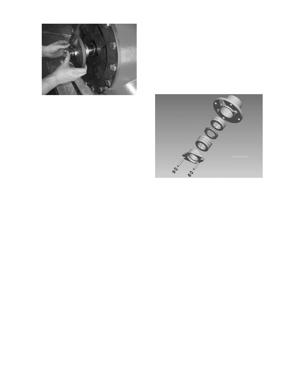
Figure 45: Installing the Gland Assembly
7. Install the four gland assembly capscrews.
8. Install the set screws in the sleeve and tighten
to 50 inch-lbs.
9. Install the slinger.
10. Repeat steps 1 through 9 to install the seal on
the other side. When finished, see the section
entitled Assembly Procedure to Install
Bearing Frames – All Pumps.
ASSEMBLY PROCEDURE TO INSTALL
STUFFING BOX AND PACKING
1. Place stuffing box, wetted end down, onto the
bench and slide the sleeve through stuffing
box bore letting it set onto bench
2. Install packing rings over the sleeve and down
into the bore so that the ends butt, leaving no
gap between the packing and stuffing box.
Press the packing to the bottom of the stuffing
box. Stagger the joints of each packing ring at
least 90°.
NOTE: On a flushed stuffing box, the lantern
ring will replace the third packing ring from
the bottom, requiring only five rings of
packing per side. (See Figure 30.) The
lantern ring must be aligned with the seal
water inlet when the packing is compressed.
On non-flushed (plugged) stuffing boxes, a
sixth ring of packing is supplied for each side
and takes the place of the lantern ring.
3. Apply anti-seize compound only to the area of
the shaft that will be under the sleeve.
4. Place the stuffing box gasket on the stuffing
box. Grease may be used to hold the gasket
in place.
5. Slide the sleeve/stuffing box subassembly
over the shaft until the sleeve bottoms out
onto the shaft locating shoulder.
6. Install the four stuffing box capscrews.
7. Install set screws in the sleeve and tighten to
50 inch-lbs.
NOTE: The last ring in each box may not be
required until after the pump has operated for a
period of time.
8. Assemble the glands, studs, washers, and
nuts square with the stuffing box and pull up
tight. (See Figure 46 of an exploded
assembly.)
Figure 46: Exploded View of Stuffing Box with
Lantern Ring
9. Repeat steps 1 through 8 for the other side.
When finished, see the section entitled
Assembly Procedure to Install Bearing
Frames – All Pumps.
NOTE: After the bearing frame has been installed,
loosen the nuts to permit the packing to expand.
Retighten until finger tight. Final adjustment of the
gland nuts must be done while the pump is
running. Allow approximately 30 minutes between
adjustments. A good adjustment should allow
approximately one drip per second.
ASSEMBLY PROCEDURE TO INSTALL
CARTRIDGE SEALS
1. Apply anti-seize compound only to the area of
the shaft that will be under the sleeve.
2. If installing an entire cartridge seal, place the
gasket onto the gland of the cartridge seal.
(See Figure 47.) Grease may be used to hold
the gasket in place. Slide the complete
assembly over the shaft until the gland fully
seats into the coverplate bore. Install and
tighten the four cartridge seal capscrews.
Push the sleeve fully home to axial stop and
tighten set screws to 130 inch-lbs.