Bell & Gossett P5002169C Series VSCS User Manual
Page 10
8
3. Hold one half element on the hubs to
determine the appropriate hub spacing. If
using spacer elements with high speed
rings, hold both half elements on the hubs
to make sure the hubs do not interfere
with the rings. The hubs may be installed
with the hub extension facing in or out.
Make sure the shaft extends into the hubs
at least .8 times the diameter of the shaft.
4. Lightly fasten the hubs to the shafts to
prevent them from moving during
alignment.
5. The hubs should be aligned to at least the
values shown in Figure 10 for allowable
misalignments. Alignment may be done
with lasers, dial indicators, or with a
straight edge and calipers.
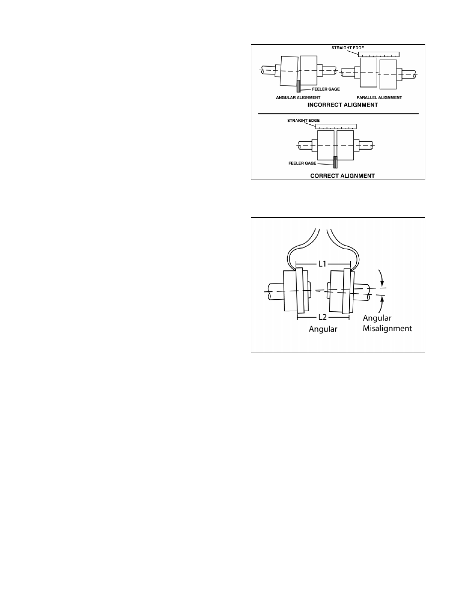
To align using straight edge and calipers
Angular misalignment may be checked by
using a caliper to gauge the distance
between the two hubs at various points
around the circumference. Do not rotate the
shafts. Reposition the equipment until the
difference between the minimum and
maximum distance values is within the
permissible value.
Angular misalignment may also be checked
by inserting feeler gauges between the
coupling faces at various points around the
circumference. Do not rotate the shafts.
Reposition the equipment until the difference
between the minimum and maximum
distance values is within the permissible
value.
Parallel alignment may be checked by placing
a straight edge across the two hubs and
measuring the maximum offset at various
points around the periphery of the hubs. Do
not rotate the shafts. Reposition equipment
until the offset is within the permissible value.
Figure 8: Checking Alignment with
Straight Edge
Figure 9: Checking Alignment with Calipers