Bell & Gossett P5002169C Series VSCS User Manual
Page 31
29
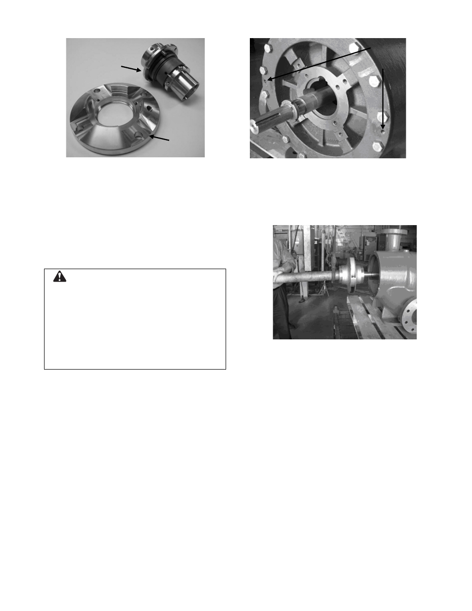
Figure 33: Cartridge Seal Gland and Service
Kit (Cassett and Sleeve)
6. If only the cartridge seal or cartridge seal
cassette is to be replaced, proceed to the
section entitled Assembly Procedure to
Install Cartridge Seals.
7. If disassembly of the pump is required,
proceed to the section entitled Disassembly
Procedure to Remove Coverplates and
Shaft Assembly – All Pumps.
CAUTION: Equipment Damage
To prevent premature seal failure or possible
injury, the unitized seals should not be used as an
alternate or substitute for the balanced seals
installed in a high suction pressure rated VSX
pump.
Failure to follow these instructions could result in
serious property damage and/or moderate
personal injury.
DISASSEMBLY PROCEDURE TO REMOVE
COVERPLATES AND SHAFT ASSEMBLY – ALL
PUMPS
1. Ensure shaft threads are protected using tape
or nuts. (See Figure 34.)
2. Remove the volute capscrews. Using jacking
screws, pull the coverplate from the volute.
(See Figure 34.)
Figure 34: Removing the Coverplate Using
Jacking Screws
3. Remove the volute gasket.
4. Pull the impeller and shaft assembly from the
volute. (See Figure 35.)
Figure 35: Removing the Shaft Assembly
5. Repeat steps 2 through 4 to remove the other
coverplate.
6. Remove the impeller retaining rings.
7. The impeller is press fitted on the shaft. The
use of a press is required for removing and
mounting the impeller to the shaft.
8. Remove the impeller key from the shaft.
ASSEMBLY PROCEDURE TO INSTALL
COVERPLATES AND SHAFT ASSEMBLY – ALL
PUMPS
NOTE: Inspect all parts for wear and damage.
Replace where needed.
1. Insert the impeller key into the shaft key slot.
2. Install the first impeller retaining ring. (See
Figure 36.)
Jacking
Screw
Holes
Cassette and
Sleeve
Gland