Bell & Gossett P5002169C Series VSCS User Manual
Page 33
31
Figure 40: View of the pump interior after one
coverplate has been installed
8. Install the volute capscrews.
NOTE: Refer to Table 6 for all capscrew torque
requirements.
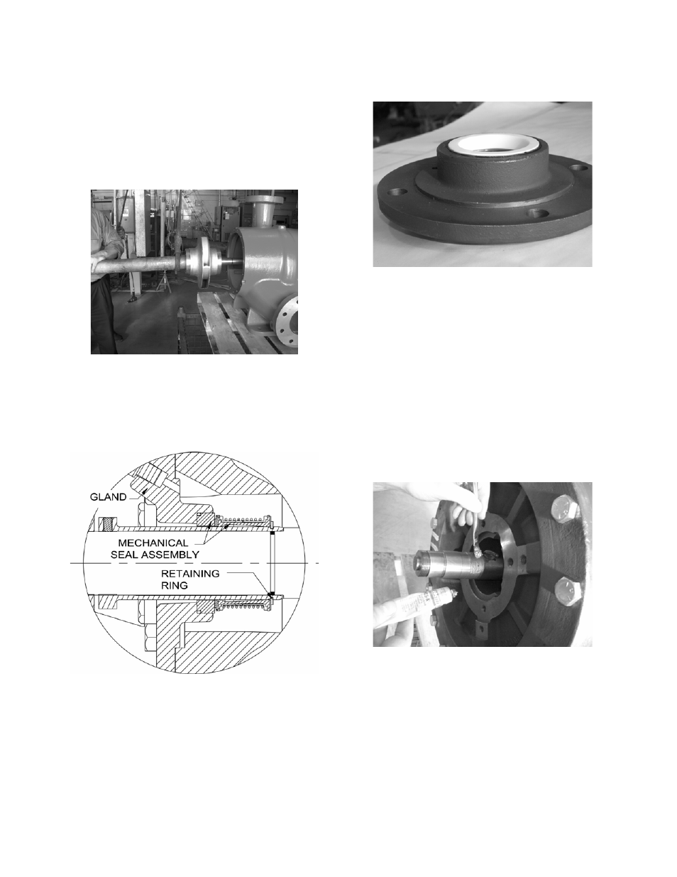
9. Insert the shaft assembly into the volute. (See
Figure 41.) Ensure that the shaft threads are
protected using tape or nuts. (See Figure 34.)
Figure 41: Installing the Shaft Assembly
10. Repeat steps 6 through 8 to install the second
coverplate.
ASSEMBLY PROCEDURE TO INSTALL
STANDARD MECHANICAL SEALS
Figure 42: Standard Mechanical Seal Cross
Section
1. Press the stationary mechanical seal seat into
the gland bore. (See Figure 43.) To ease
assembly, lightly lubricate the bore with P-80
Rubber Lubricant Emulsion, soapy water, or
equivalent.
NOTE: Handle the seals with care. Clean the
glands and seals before assembly. Take care not
to damage the seals during assembly.
Figure 43: The Seal Seat Installed in the Gland
2. Slide the gland assembly over the shaft
sleeve.
3. Lightly lubricate the shaft sleeve with P-80
Rubber Lubricant Emulsion, soapy water, or
equivalent and slide the mechanical seal head
onto the sleeve.
4. While pushing down on the mechanical seal
head, install the retaining ring into the shaft
sleeve groove.
5. Apply anti-seize compound only to the area of
the shaft that will be under the sleeve. (See
Figure 44.)
Figure 44: Applying Anti-seize Compound to
the Shaft
6. Place the gland gasket onto the gland. Grease
may be used to hold the gasket in place. Slide
the complete assembly over the shaft until the
sleeve bottoms out onto the shaft locating
shoulder. (See Figure 45.)