Bell & Gossett P5002169C Series VSCS User Manual
Page 28
26
GENERAL DISASSEMBLY PROCEDURES
SHUTDOWN
The following steps will address most normal
shutdowns of the pump, such as maintenance.
Make any further adjustments of process piping,
valves, etc., as required.
1. Shut down the pump driver. (Consult
manufacturer’s instructions for special
operations.)
WARNING: Unexpected Startup Hazard
Disconnect and lockout power before servicing.
Failure to follow these instructions could result in
serious personal injury or death, or property
damage
.
2. Close the suction and discharge valves.
3. For pumps equipped with external flush, close
the flush line valves. However, to prevent
contaminating the packing, leave these lines
open, unless the pump is completely drained.
4. Open the drain valves and casing vents as
required.
CAUTION: Extreme Temperature Hazard
Allow pump temperatures to reach acceptable
levels before proceeding. Open the drain valve.
Do not proceed until liquid stops coming out of the
drain valve. If liquid does not stop flowing from the
drain valve, isolation valves are not sealing and
should be repaired before proceeding. After liquid
stops flowing from drain valve, leave the valve
open and continue. Remove the drain plug located
on the bottom of the pump housing. Do not
reinstall the plug or close the drain valve until
reassembly is completed.
Failure to follow these instructions could result in
moderate personal injury or property damage.
DISASSEMBLY PROCEDURE TO REMOVE
BEARING FRAMES – ALL PUMPS
1. Remove the coupling guard. See the Guards
section.
2. Remove the capscrews that secure the
coupling element to the hubs. Remove the
coupling element. Depending on the type of
coupling, proceed to step a or step b.
a. For
non-spacer
coupling
assemblies: move the driver to
allow sufficient access for
maintenance and remove the
coupling hub on the pump.
b. For spacer coupling assemblies:
remove the coupling hub on the
pump.
3. Remove the four capscrews from the bearing
cap.
4. Remove the four bearing bracket capscrews.
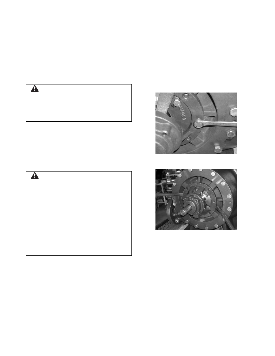
5. Remove the bearing bracket using jacking
screws. (See Figure 23.) Pry bars may also be
used. (See Figure 24.)
Figure 23:
Removing the Outboard Bearing
Bracket Using Jacking Screws
Figure 24:
Removing the Inboard Bearing Bracket
Using Pry Bars
6. Bend back the lockwasher tab and remove the
locknut and lockwasher.
7. Remove the bearing with pullers. (See Figure
25.) A universal fixture kit (part number
AC2394) may also be used. (See Figure 26.)
The universal fixture kit should not be used on
pumps with 2” frames as the bearing backup
ring may damage the bearing cap’s lip seal.
(See Figure 27 for a listing of pump sizes with
2” frames.)