Bell & Gossett P5002169C Series VSCS User Manual
Page 17
15
times, be supplied with flushing liquid at a high
enough pressure to keep the box free from foreign
matter, which would quickly destroy the packing
and score the shaft sleeve.
Only a sufficient volume of flushing liquid to create
a definite direction of flow from the stuffing box
inward to the pump casing is required, but the
pressure is important. Apply seal water at a rate of
approximately .25 GPM at a pressure
approximately 15 to 20 psig above the suction
pressure. (Approximately one (1) drop per
second.)
External flushing liquid should be adjusted to the
point where the packing runs only slightly warm,
with a very slow drip from the stuffing box. Excess
pressure from an external source can be very
destructive to packing. More pressure is required,
however, for abrasive slurries than for clear
liquids. Examination of the leakage will indicate
whether to increase or decrease external
pressure. If slurry is present in the leakage,
increase the pressure until only clear liquid drips
from the box. If the drippage is corrosive or
harmful to personnel, it should be collected and
piped away.
A common error is to open the external piping
valve wide and then control the drippage by
tightening the packing gland. A combination of
both adjustments is essential to arrive at the
optimum condition. The life of packing and sleeve
depends on careful control more than any other
factor.
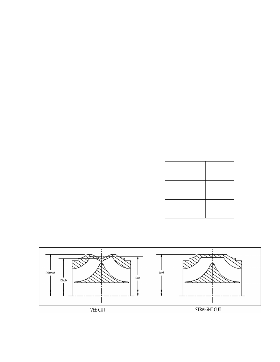
VEE-CUT IMPELLER TRIMS
A vast majority of the impeller trims are standard
straight cuts. However, on several pump sizes a
vee-cut is employed for the smaller diameters.
(See Figure 17.) For either type of cut, D
ref
is the
impeller diameter on the nameplate which is
chosen from the published performance curves.
A vee-cut is required when the impeller diameter
D
ref
is smaller than the D
shroud
values shown in
Table 5.
D
shroud
is the trim diameter of the shrouds. This
value, as shown in Table 5, is constant for all vee-
cut diameters for a given pump size.
D
hub
is the diameter at the hub (bottom of the vee-
cut).
To achieve the performance for a given D
ref
, trim
D
shroud
to the values in Table 5. Then using the
charts in Figure 18, find D
hub
for the appropriate
pump size and D
ref
.
Example: to trim an 8x10x10.5A impeller to a D
ref
of 8.000, trim the shrouds to 8.250” (D
shroud
) per
Table 5, and trim the bottom of the vee to 7.750”
(D
ref
) per Figure 18.
Table 5: Required Vee-cuts
Pump Size
D
shroud
6x8x10.5A 8.000
in.
8x10x10.5A 8.250
in.
10x12x10.5A 9.750
in.
12x14x13.5A 11.125
in.
14x16x13.5A 12.375
in.
Figure 17: Straight and Vee-cut Impellers