Goulds Pumps 3700 - IOM User Manual
Page 97
Maintenance
Install the cartridge-type mechanical seal and seal-chamber cover
NOTICE:
Refer to the mechanical seal manufacturer’s drawings and instructions for assistance during
the installation of the mechanical seal.
1. Remove the impeller.
a) Loosen and remove the impeller nut.
The impeller nut has left-hand threads.
b) Remove the impeller, impeller key, and seal-chamber cover as described in the
Disassembly section.
2. Lubricate all O-rings with suitable lubricant, unless the seal manufacturer’s instructions
indicate otherwise.
3. Slide the cartridge seal assembly (rotary, stationary gland, gland gasket, and sleeve) onto
the shaft.
NOTICE:
Ensure that the mechanical-seal gland-piping connections are properly oriented.
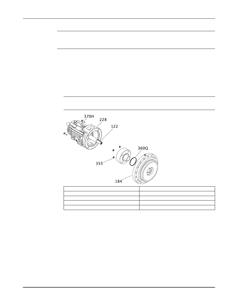
122
Shaft
184
Seal-chamber cover
228
Bearing frame
355
Gland stud nut
370H
Bearing-frame bolts
4. Install the seal-chamber cover.
a) Set up a sling to the eyebolt and to the overhead lifting device.
b) Lift the seal-chamber cover and position it so that it aligns with the shaft.
c) Install the seal-chamber cover on the power end by guiding the cover carefully over the
cartridge-seal rotary.
Ensure that the gland studs smoothly enter the holes in the cartridge-seal gland and
that the cover fits into the bearing frame lock.
d) Install the seal-chamber cover and bearing-frame bolts and tighten them using an
alternating pattern.
Torque the bolts to the values shown in the Maximum torque values for 3700 fasteners
table.
e) Install the gland stud nuts and tighten evenly to the torque values shown in the
Maximum torque values for 3700 fasteners table.
5. Tighten the setscrews in the locking collar.
Model 3700, API Type OH2 / ISO 13709 1st and 2nd Ed. / API 610 8/9/10/11th Ed. Installation, Operation, and Maintenance
95
Manual