Goulds Pumps 3700 - IOM User Manual
Page 79
Maintenance
NOTICE:
• All replacement impeller wear rings, except those that are hard-faced, are supplied
0.020 in. to 0.030 in. (0.51 mm to 0.75 mm) oversize.
• Do not machine all wear rings. Spare hard-faced impeller wear rings are supplied to
pre-established clearances when both impeller and casing wear rings are renewed.
10. Install the impeller:
a) Install the impeller key on the shaft of the assembled bearing frame from which the
seal-chamber cover has been removed, and on which the runouts are within the
established specifications. The key should be at the top (12 o’clock) position for the
impeller installation.
b) Install the impeller on the shaft.
c) Install the impeller washer.
d) Secure the impeller firmly with an impeller screw or impeller nut.
The impeller screw has left-hand threads.
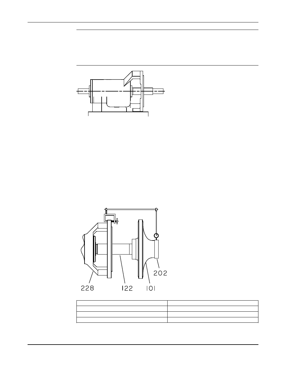
11. Check the impeller wear-ring runout:
a) Mount the dial indicator.
b) Rotate the shaft so that the indicator rides along the casing-side impeller wear-ring
surface for 360°.
c) Repeat steps a and b for the wear ring on the seal-chamber cover side.
101
Impeller
122
Shaft
202
Casing-side impeller wear-ring
228
Seal-chamber cover side wear ring
If the impeller wear ring runout is in excess of 0.005 in. (0.13 mm):
Model 3700, API Type OH2 / ISO 13709 1st and 2nd Ed. / API 610 8/9/10/11th Ed. Installation, Operation, and Maintenance
77
Manual