Replace the wear rings – Goulds Pumps 3700 - IOM User Manual
Page 76
Maintenance
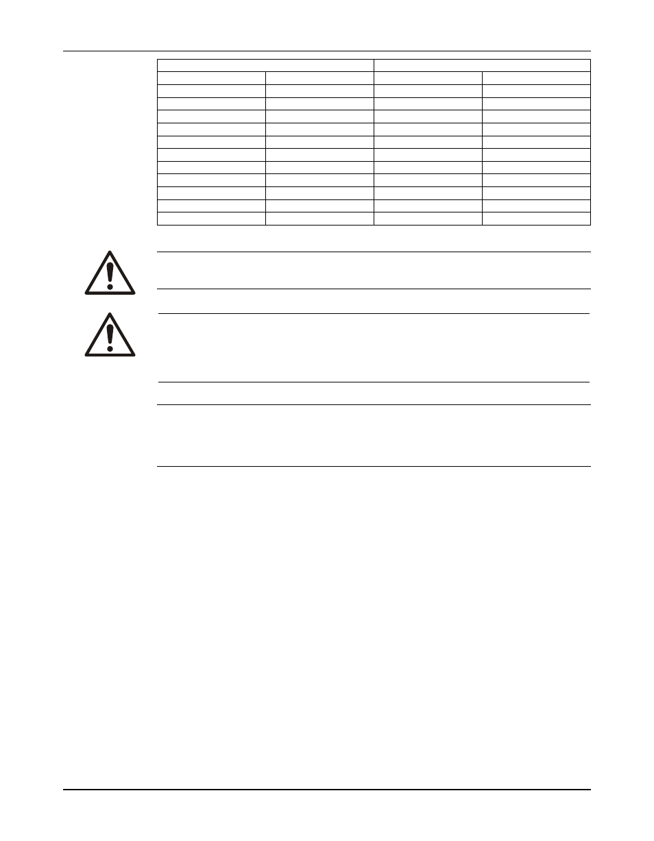
Diameter of impeller wear ring
Minimum diametrical clearance
3.000 to 3.499
80 to 89.99
0.013
0.33
3.500 to 3.999
90 to 99.99
0.014
0.35
4.000 to 4.499
100 to 114.99
0.015
0.38
4.500 to 4.999
115 to 124.99
0.016
0.40
5.000 to 5.999
125 to 149.99
0.017
0.43
6.000 to 6.999
150 to 174.99
0.018
0.45
7.000 to 7.999
175 to 199.99
0.019
0.48
8.000 to 8.999
200 to 224.99
0.020
0.50
9.000 to 9.999
225 to 249.99
0.021
0.53
10.000 to 10.999
250 to 274.99
0.022
0.55
10.000 to 11.999
275 to 299.99
0.023
0.58
12.000 to 12.999
300 to 324.99
0.024
0.60
Replace the wear rings
WARNING:
Dry ice and other chilling substances can cause physical injury. Contact the supplier for information and
advice for proper handling precautions and procedures.
CAUTION:
• Excessive machining can damage ring fits and render parts unusable.
• Wear insulated gloves when you handle rings. Rings will be hot and can cause physical injury.
• For runout checks, firmly support the bearing-frame assembly in the horizontal position.
• Wear heavy work gloves when you handle impellers. The sharp edges can cause physical injury.
NOTICE:
The impeller and wear-ring clearance setting procedures must be followed. Improperly setting
the clearance or not following any of the proper procedures can result in sparks, unexpected
heat generation, and equipment damage.
Casing, impeller, and seal chamber cover wear rings are held in place by a press fit and three
set screws.
1. Remove the wear rings:
a) Remove the set screws.
b) Remove the wear rings from the casing, impeller, and seal-chamber cover using a pry
or puller to force the rings from the fits.
2. Clean the wear-ring seats thoroughly, and make sure that they are smooth and free of
scratches.
74
Model 3700, API Type OH2 / ISO 13709 1st and 2nd Ed. / API 610 8/9/10/11th Ed. Installation, Operation, and Maintenance
Manual