American Electric Lighting CVL User Manual
Page 3
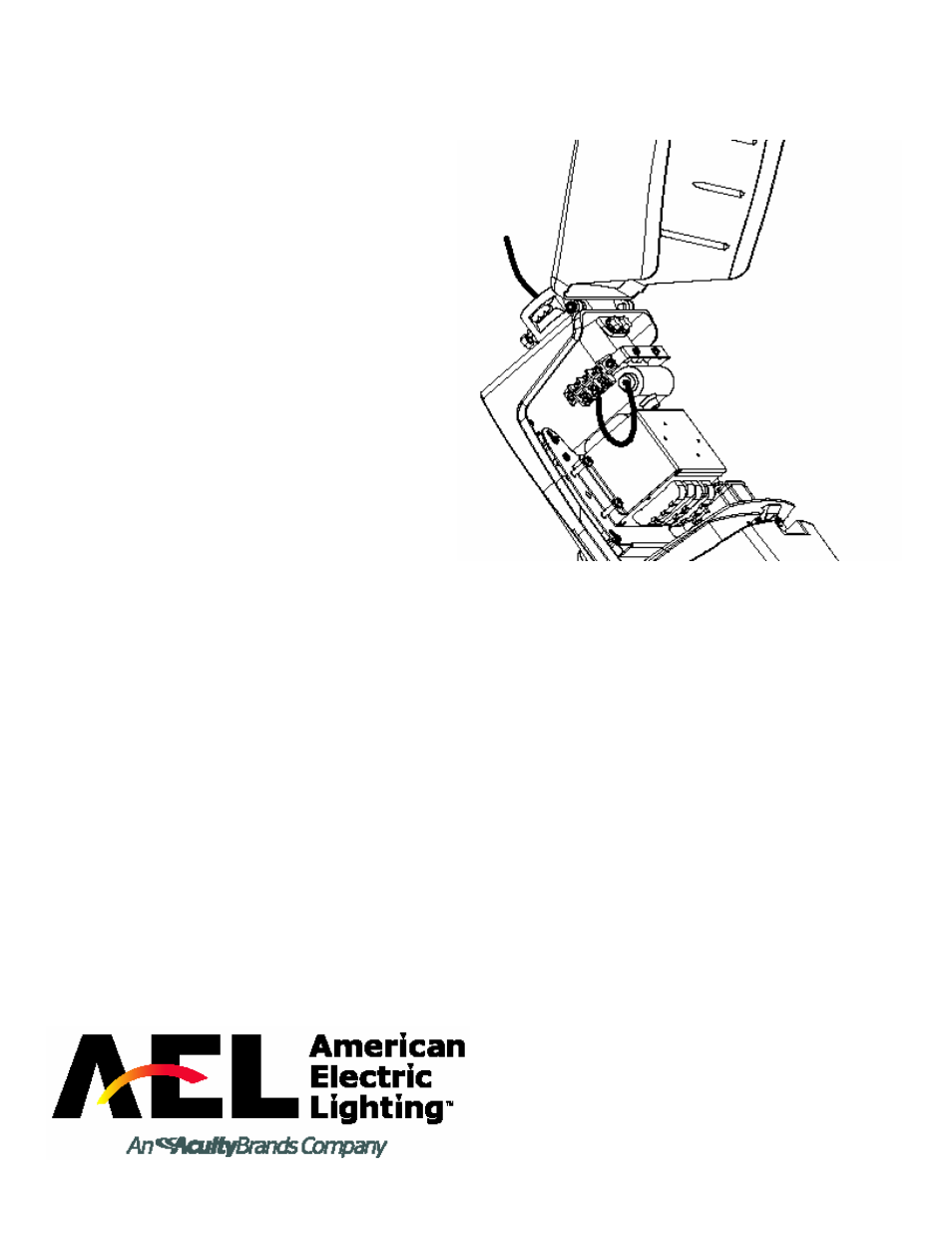
WIRING:
WIRING:
WIRING:
WIRING:
Note: This procedure is not necessary if unit is supplied with
pre-wire.
1. Open the ballast compartment.
2. Locate the wiring diagram attached to the inside of the
hood.
3. Using the wiring diagram as a guide, connect the power
supply leads to the terminal block.
4. Connect the green ground supply wire to the casting by
hooking it around the head of the green grounding screw,
located beside the terminal block, and tightening the screw
securely.
5. Close the unit.
PHOTOCONTROL:
PHOTOCONTROL:
PHOTOCONTROL:
PHOTOCONTROL:
NOTE: On the CVL no tooling is necessary for the
photocontrol installation or adjustment.
1. Insert the photocontrol into the receptacle.
2. Turn the photocontrol toward north by lifting and turning
simultaneously until it is facing north.
Note: For electrical safety purposes, the photo control
receptacle is designed so that it will not turn beyond 360
degrees. Depending on the initial orientation, it may be
necessary to turn it in the other direction if it stops and
refuses to turn.