Cabling the switch – Allied Telesis AT-8326GB User Manual
Page 55
AT-8326GB Installation Guide
55
Cabling the Switch
Perform the following procedure to connect the data cables to the
switch ports. Refer to Required Cables on page 45 for cable
specifications.
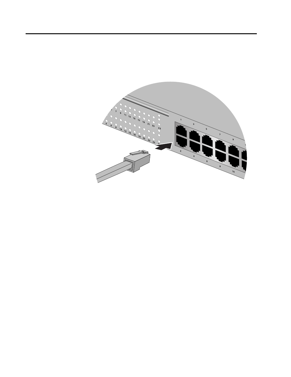
1. Connect the data cables to the RJ-45 ports on the switch, as shown in
Figure 28 Connecting the Data Cables
When connecting a cable to a port on the switch, observe the
following guidelines:
G An RJ-45 connector should fit snugly into the port on the switch.
The tab on the connector should lock the connector into place.
G Do not connect a port on the switch to a phone jack. Doing so can
damage the switch.
G Since the RJ-45 ports on the switch are auto-MDI/MDI-X, you can
use either straight-through or cross-over twisted pair cables to
connect the network devices.
G If your network topology will contain a loop where two or more
network devices can communicate with each other over more
than one data path, do not connect the network cables forming
the loop until after you have activated the Spanning Tree Protocol
(STP) on the switch. Data loops can adversely affect network
performance. For instructions on how to activate STP, refer to the
AT-S41 Management Software User’s Guide.
LNK/ACT
FDX/COL
GIGA
LNK/ACT
GIGA
FDX/COL