Allied Telesis ALLIEDVIEW-UM 1.6 User Manual
Page 14
Allied Telesis
AlliedView-UM
1.6
User's Guide
PN 613-000381 Rev B
Page 14 of 129
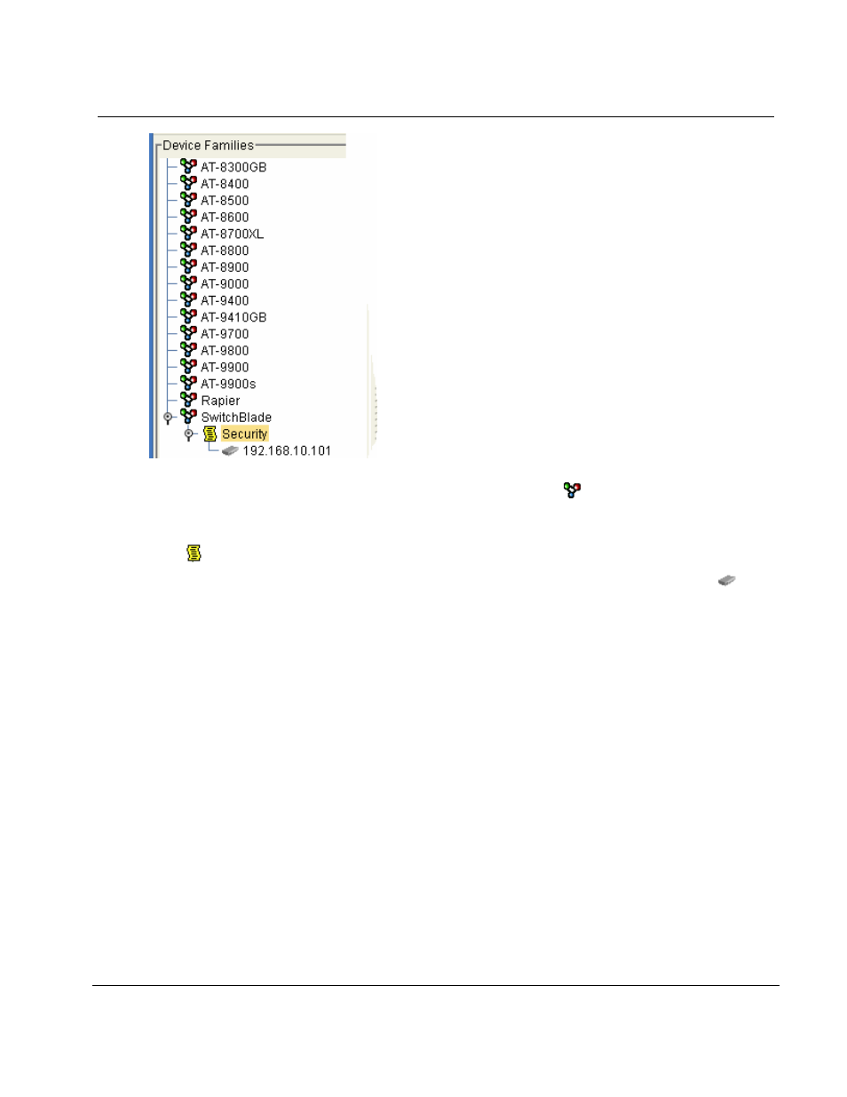
The root nodes of the Device Families represent the AT Device Families that are currently supported by
this application. The AT Device Family root node is represented by a ( ) icon followed by the AT Device
Family name.
Each AT Device Family root node can contain Device Group nodes. A Device Group node is represented
by a (
) icon followed by the Device Group name.
Finally, a Device Group node can contain Device nodes. A Device node is represented by a (
) icon
followed by the IP address of that device. A Device node cannot contain any other nodes under it.
Double clicking on a node will display the corresponding dialog box that will allow you to perform
functions pertaining to that node. For instance, if you double click on a Device Node, the Edit Device
dialog box will be displayed. From the Edit Device dialog box you can view and modify some of the
device attributes.
3.2 OPERATIONS
SELECTION
PANE
The Operations Selection Pane allows you to select an operation profile to create.