Mode selection button, Figure 8: mode selection button, Chapter 1: overview 36 – Allied Telesis AT-MCF2012LC/1 User Manual
Page 36: Class 1 led product, Tx rx 2 cdc
Chapter 1: Overview
36
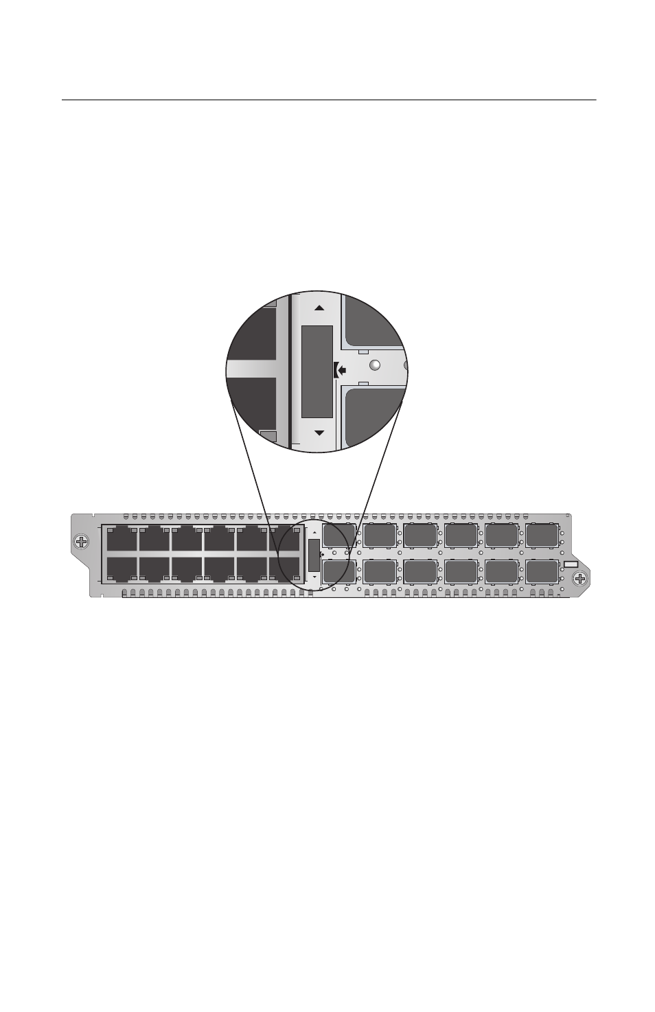
Mode Selection Button
The Mode Selection button shown in Figure 8 serves two
purposes. One is to set the operating mode of a channel.
The three operating modes are described in “Channel
Operating Modes” on page 31. The other is to view the
duplex mode and collisions on the ports of a channel with
the CDC and FDC LEDs, explained in “CDC and FDC
Duplex Mode and Collision LEDs” on page 28,
Figure 8. Mode Selection Button
Before you can set the operating mode of a channel or view
the duplex mode and collisions on the ports of a channel,
you must first select the channel. You accomplish this by
turning the Mode Selection button up or down to toggle
through the channels. Channel selection is indicated by the
CH LEDs beneath the fiber optic ports. You can select only
one channel at a time.
After you have selected a channel, the duplex mode setting
and collisions on the two ports of the selected channel are
immediately reflected on the CDC and FDC LEDs.
To set the operating mode of a channel, press the middle of
the button to toggle the channel between Link Test (LT),
MissingLink (ML), and Smart MissingLink (SML). The
operating mode of a channel is reflected by the LT, ML, and
L
A
L
A
CH
CH
CH1
CH2
L
A
L
A
CH3
CH4
L
A
L
A
CH5
CH6
L
A
L
A
CH7
CH8
L
A
L
A
CH9
CH10
L
A
L
A
CH11
CH12
TX
RX
1
TX
RX
TX
RX
TX
RX
2
3
4
5
6
7
8
9
10
11
12
CDC
FDC
LT
ML
SML
L
A
1
L
A
2
3
4
5
6
7
8
9
10
11
12
L
A
L
A
A
T
-MCF2012LC
CLASS 1
LED PRODUCT
CH
CH
TX
RX
2
CDC