Cdc and fdc duplex mode and collision leds, Al a ch ch, Chapter 1: overview 28 – Allied Telesis AT-MCF2012LC/1 User Manual
Page 28: Ch1 tx rx 2 4 cdc fdc
Chapter 1: Overview
28
CDC and
FDC Duplex
Mode and
Collision
LEDs
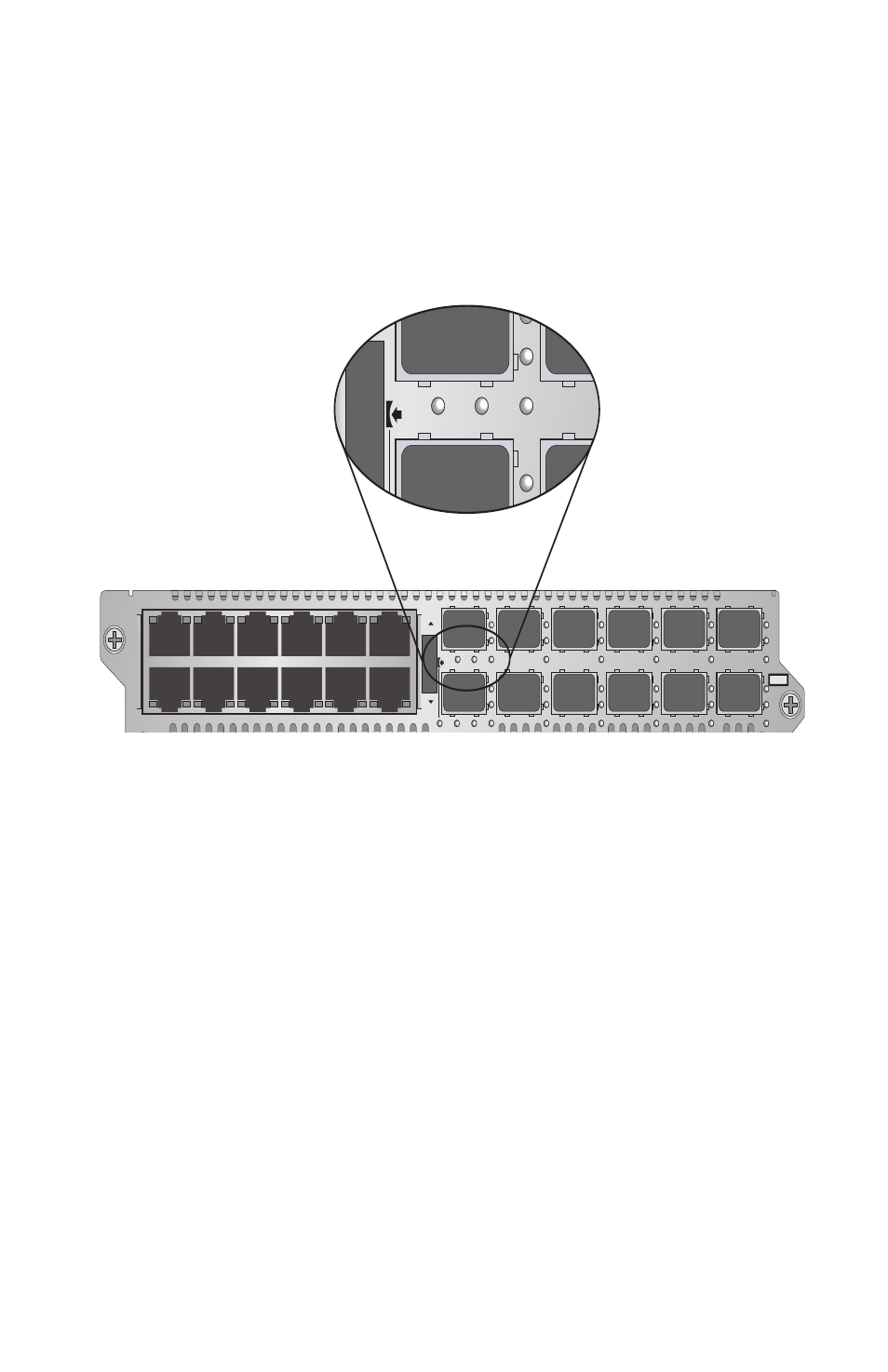
The CDC and FDC LEDs shown in Figure 7 display the
duplex mode of the ports in a channel and, for ports
operating in half-duplex mode, the collisions. The CDC
(Copper, Duplex mode, Collisions) LED displays this
information for the twisted pair port of a channel, while the
FDC (Fiber optic, Duplex mode, Collisions) LED displays
the same information for the fiber optic port.
Figure 7. CDC and FDC Duplex Mode and Collisions LEDs
The LEDs can display the status of the ports of only one
channel at a time. To use the LEDs you must first select a
channel with the Mode Selection button, explained in “Mode
Selection Button” on page 36. The selected channel is
indicated with the CH LEDs beneath the fiber optic ports.
The CDC and FDC LEDs display the status of a channel’s
ports as soon as a channel is selected. For example, if you
select channel 4 (CH4), the CDC and FDC LEDs reflect the
duplex mode and collisions for twisted pair port 4 and fiber
optic port 4 on the module, respectively.
A
L
A
CH
CH
CH1
TX
RX
2
4
CDC
FDC
L
A
L
A
CH
CH
CH1
CH2
L
A
L
A
CH3
CH4
L
A
L
A
CH5
CH6
L
A
L
A
CH7
CH8
L
A
L
A
CH9
CH10
L
A
L
A
CH11
CH12
TX
RX
1
TX
RX
TX
RX
TX
RX
2
3
4
5
6
7
8
9
10
11
12
CDC
FDC
LT
ML
SML
L
A
1
L
A
2
3
4
5
6
7
8
9
10
11
12
L
A
L
A
A
T
-MCF2012LC
CLASS 1
LED PRODUCT