Media converter channels, Figure 4: channel 1 on the media converter module, Class 1 led product – Allied Telesis AT-MCF2012LC/1 User Manual
Page 19
AT-MCF2012LC and AT-MCF2012LC/1 Media Converter Modules Installation Guide
19
Media Converter Channels
The AT-MCF2012LC and AT-MCF2012LC/1 modules have
twelve independent media converter channels. Each
channel forwards Fast Ethernet network traffic between one
10/100Base-TX twisted pair port and one 100Base-FX fiber
optic port.
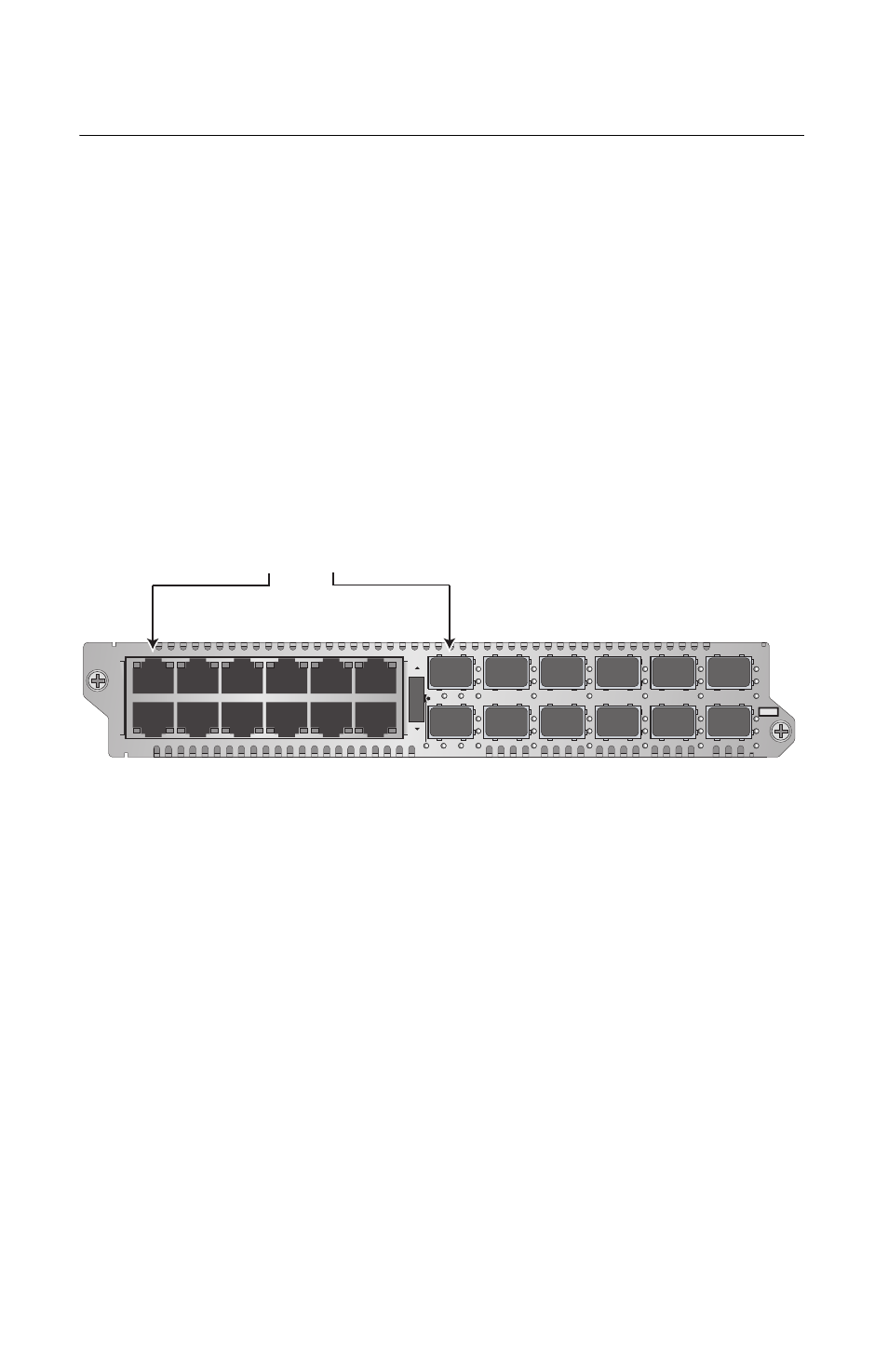
The channels are predefined. Channel 1 consists of twisted
pair port 1 and fiber optic port 1 (as shown in Figure 4),
channel 2 of twisted pair port 2 and fiber optic port 2, and so
forth. The port assignments of the channels cannot be
changed.
Figure 4. Channel 1 on the Media Converter Module
Each channel operates independently of the other channels
on the same module and from channels on other modules in
the same chassis. As such, the traffic on the two ports of a
channel cannot crossover to the ports of another channel.
A channel uses “store and forward” to transfer packets
between its two ports. A packet is forwarded to the egress
port of a channel after it has been fully received and
buffered on the ingress port and checked for CRC errors.
Packets without a CRC error are forwarded to the egress
port where CRC is regenerated prior to the transmission of
the packet, while packets with CRC errors are discarded to
prevent their propagation on the network.
Channel 1
Twisted Pair Port 1 and
Fiber Optic Port 1
L
A
L
A
CH
CH
CH1
CH2
L
A
L
A
CH3
CH4
L
A
L
A
CH5
CH6
L
A
L
A
CH7
CH8
L
A
L
A
CH9
CH10
L
A
L
A
CH11
CH12
TX
RX
1
TX
RX
TX
RX
TX
RX
2
3
4
5
6
7
8
9
10
11
12
CDC
FDC
LT
ML
SML
L
A
1
L
A
2
3
4
5
6
7
8
9
10
11
12
L
A
L
A
A
T
-MCF2012LC
CLASS 1
LED PRODUCT
1119