Figure 13: installing the at-mcf2kfan fan module – Allied Telesis AT-MCF2000 User Manual
Page 33
AT-MCF2000 Multi-channel Media Converter Chassis Installation Guide
33
3.
Remove the AT-MCF2KPNL2 blank panel from one of
the power supply/fan module slots on the back panel of
the chassis by loosening the two captive screws on the
panel with a cross-head screwdriver. Refer to Figure 8
on page 29. The fan module can be installed in either
of the power supply/fan module slots.
Note
Do not remove a blank panel from the chassis until
you are ready to install a module, especially if the
device is powered on. An open slot allows dust to
enter the unit and impedes the ability of the chassis to
maintain proper airflow and cooling.
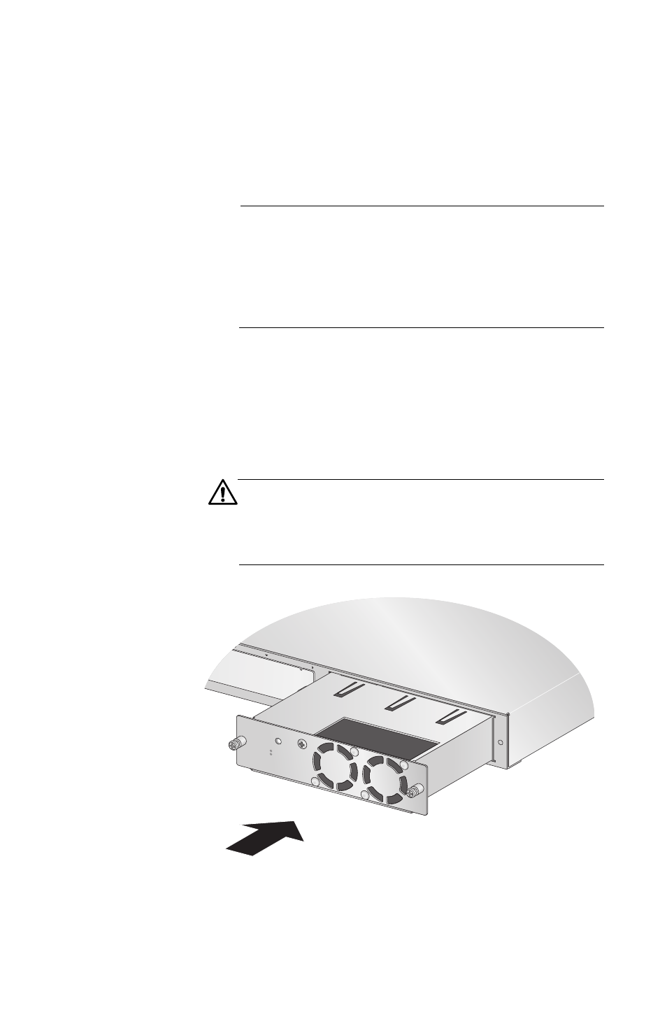
4.
Slide the fan module into the slot as shown in Figure
13, until it is flush with the back panel of the chassis.
You may need to exert light pressure to seat the
module in the connector on the back panel of the
chassis.
Caution
Do not force the module into place. Doing so may
damage the connector pins on the backplane inside
the chassis.
Figure 13. Installing the AT-MCF2KFAN Fan Module
1125-a
MANA
GEME
NT
B
AT-MCF2KF
AN
NORM
AL
FAULT
STATU
S