Chapter 1, Overview, Ter 1: overview – Allied Telesis AT-MCF2000 User Manual
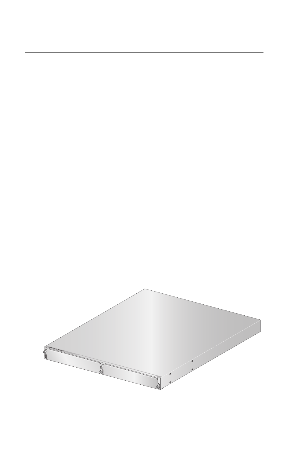
Page 13: Figure 1: at-mcf2000 chassis
13
Chapter 1
Overview
This chapter contains the following sections:
“Hardware Features” on page 15
“Media Converter Module Slots” on page 16
“Management Module Slot” on page 16
“Power Supply Module and Fan Module Slots” on
page 19
The AT-MCF2000 chassis, shown in Figure 1, and the
AT-MCF2000 series of multi-channel media converter
modules are designed to interconnect Ethernet networking
devices over large distances by transferring Ethernet
network packets between twisted pair cable and fiber optic
cable.
The chassis can accommodate two multi-channel media
converter modules as well as the optional AT-MCF2000M
Management Module for either local (out-of-band) or
remote (in-band) network management of the ports on the
media converter modules. The unit also features slots for
two power supply units for power redundancy or one power
supply unit and one fan unit. You can install the unit on a
table or in a standard 19-inch rack.
Figure 1. AT-MCF2000 Chassis
AT-M
CF
200
0
1
2
1106-a
AT-MC
F2KPN
L1
AT-MC
F2KPN
L1
A
T
-MCF2000