Unpacking the switch, Figure 18: components of the switch – Allied Telesis AT-x510DP-52GTX User Manual
Page 55
x510 Series Installation Guide for Virtual Chassis Stacking
55
Unpacking the Switch
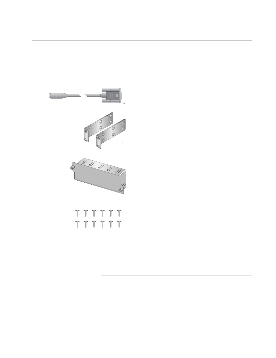
Figure 18 lists the items that come with the switch. If any item is missing or
damaged, contact your Allied Telesis sales representative for assistance.
Figure 18. Components of the switch
Note
You should retain the original packaging material in the event you
need to return the unit to Allied Telesis.
After checking the contents of the shipping containers, go to Chapter 4,
“Installing the Switch and its Power Supplies” on page 57
1947
Two rack mounting brackets
One 2 m (6.6 ft) local management cable with
RJ-45 (8P8C) and DB-9 (D-sub 9-pin)
connectors.
2047
Twelve rack mounting bracket
screws
AT-PNL250
One AT-PLN250 blank panel for
covering an empty power supply bay
See also other documents in the category Allied Telesis Computer hardware:
- AT-GS908M (54 pages)
- AT-x230-10GP (80 pages)
- AT-GS950/48PS (64 pages)
- AT-GS950/10PS (386 pages)
- AT-GS950/16PS (386 pages)
- AT-GS950/48PS (386 pages)
- AT-9000 Series (258 pages)
- AT-9000 Series (1480 pages)
- IE200 Series (70 pages)
- AT-GS950/48 (60 pages)
- AT-GS950/48 (410 pages)
- AT-GS950/8 (52 pages)
- AT-GS950/48 (378 pages)
- SwitchBlade x8106 (322 pages)
- SwitchBlade x8112 (322 pages)
- SwitchBlade x8106 (240 pages)
- SwitchBlade x8112 (240 pages)
- AT-TQ Series (172 pages)
- AlliedWare Plus Operating System Version 5.4.4C (x310-26FT,x310-26FP,x310-50FT,x310-50FP) (2220 pages)
- FS970M Series (106 pages)
- 8100L Series (116 pages)
- 8100S Series (140 pages)
- x310 Series (116 pages)
- x310 Series (120 pages)
- AT-GS950/24 (404 pages)
- AT-GS950/24 (366 pages)
- AT-GS950/16 (44 pages)
- AT-GS950/16 (404 pages)
- AT-GS950/16 (364 pages)
- AT-GS950/8 (52 pages)
- AT-GS950/8 (404 pages)
- AT-GS950/8 (364 pages)
- AT-8100 Series (330 pages)
- AT-8100 Series (1962 pages)
- AT-FS970M Series (330 pages)
- AT-FS970M Series (1938 pages)
- SwitchBlade x3112 (294 pages)
- SwitchBlade x3106 (288 pages)
- SwitchBlade x3106 (260 pages)
- SwitchBlade x3112 (222 pages)
- AT-S95 CLI (AT-8000GS Series) (397 pages)
- AT-S94 CLI (AT-8000S Series) (402 pages)
- AT-IMC1000T/SFP (23 pages)
- AT-IMC1000TP/SFP (24 pages)
- AT-SBx3106WMB (44 pages)