4 power through db-9 jumper – Matrix Orbital GLT240128 Legacy User Manual
Page 16
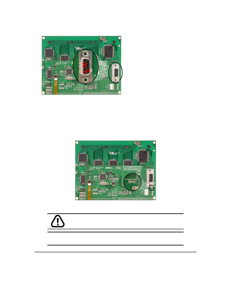
Pin
2
RX/SCL (I
2
C clock)
Pin
3
TX/SDA (I
2
C data)
Pin
5
GND
Pin
9
PWR (Must solder power through DB-9 jumper. See table 78
Figure 15: RS-232 Pin-out
2.4
Power Through DB-9 Jumper
In order to provide power through pin 9 of the DB-9 Connector you must place a solder jumper on the
Power through DB-9 Jumper pictured in Figure 16 below. The GLT240128 allows all voltage models to use
the power through DB-9 option, see table 78 for display module voltage requirements.
Figure 16: Power Through DB-9 Jumper
WARNING
Do not apply voltage through pin 9 of the DB-9 connector
AND through the Power/Data Connector at the same time.
NOTE
We do not recommend that you use pin 9 (Ring Indicator) of the PC to power the
display module. You will have to make a special DB9 cable.
Matrix Orbital
GLT240128
11
- GTT35 (19 pages)
- GTT50A (53 pages)
- GTT70A (19 pages)
- GTT38A (19 pages)
- GTT43A (19 pages)
- GTT50A (19 pages)
- GTT Example Files (2 pages)
- GX24064 (24 pages)
- GLT24064R-1U (72 pages)
- GLT24064 (71 pages)
- GLT24064 Legacy (56 pages)
- GLK24064-25 Legacy (41 pages)
- GLK24064-25 Legacy (47 pages)
- GLK24064-25 Legacy (68 pages)
- GLT240128 (70 pages)
- GLK12232-25-SM (70 pages)
- GLK12232-25-SM Legacy (41 pages)
- GLK12232-25-SM Legacy (42 pages)
- GLK12232-25-FGW (66 pages)
- GLK19264A-7T-1U (68 pages)
- GLK240128-25 Legacy (67 pages)
- GLC24064 (44 pages)
- GLC24064 (63 pages)
- GLK12232-25-WBL (39 pages)
- GLK19264-7T-1U (71 pages)
- GLK24064-16-1U (48 pages)
- VK162-12 (41 pages)
- LK162-12 Legacy (37 pages)
- LK162-12 Legacy (42 pages)
- LK162A-4T (36 pages)
- LK162B-7T (37 pages)
- VK202-25-USB (42 pages)
- LK202-25 Legacy (20 pages)
- LK202-25 Legacy (37 pages)
- LK202-25 Legacy (50 pages)
- VK204-25 (47 pages)
- LK204-25 Legacy (33 pages)
- LK204-25 Legacy (62 pages)
- LK204-7T-1U (40 pages)
- LK402-25 (43 pages)
- LK402-25 Legacy (56 pages)
- LK404-25 (37 pages)
- LK202-24-USB (36 pages)
- LK202-24-USB (48 pages)