Horner APG SmartStix HE559DQM602 User Manual
Page 2
MAN0897-01
Specifications / Installation
______________________________________________________________________________________________________
03/02/2009
Page 2 of 2 ECN # 952
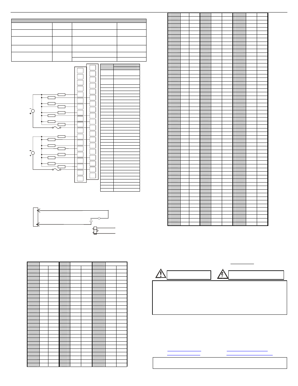
6 WIRING
DQM602 Relay Outputs
Number of output points
16
Minimum load voltage /
current
5VDC / 1mA
Commons per Module
2
Maximum Load Current
(resistive)
2.0A per channel
5.0A per common
Rated Load Voltage
24VDC,
220VAC
OFF to ON Response
10ms. Max.
Rated Voltage
11 – 25
VDC
ON to OFF Response
12ms. Max.
Output Type
N.O.
Internal power
Consumption (mA)
550mA
Weight
9.91oz. (281 g)
7 INTERNAL
WIRING
Specification for transient voltage suppressors (transorbs) used on output circuitry is
400VDC, bi-directional 400 watts.
Electro-mechanical relays comply with IEC1131-2.
8
DECIMAL (DEC) TO HEXADECIMAL (HEX) CONVERSION TABLE
Dec Hex Dec Hex Dec Hex
HI LO HI
LO HI
LO
0
0 0 86
5 6 172
A C
1
0 1 87
5 7 173
A D
2
0 2 88
5 8 174
A E
3
0 3 89
5 9 175
A F
4
0 4 90
5 A 176
B 0
5
0 5 91
5 B 177
B 1
6
0 6 92
5 C 178
B 2
7
0 7 93
5 D 179
B 3
8
0 8 94
5 E 180
B 4
9
0 9 95
5 F 181
B 5
10
0 A 96
6 0 182
B 6
11
0 B 97
6 1 183
B 7
12
0 C 98
6 2 184
B 8
13
0 D 99
6 3 185
B 9
14
0 E 100
6 4 186
B A
15
0 F 101
6 5 187
B B
16
1 0 102
6 6 188
B C
17
1 1 103
6 7 189
B D
18
1 2 104
6 8 190
B E
19
1 3 105
6 9 191
B F
20
1 4 106
6 A 192
C 0
21
1 5 107
6 B 193
C 1
22
1 6 108
6 C 194
C 2
23
1 7 109
6 D 195
C 3
24
1 8 110
6 E 196
C 4
25
1 9 111
6 F 197
C 5
26
1 A 112
7 0 198
C 6
27
1 B 113
7 1 199
C 7
28
1 C 114
7 2 200
C 8
29
1 D 115
7 3 201
C 9
30
1 E 116
7 4 202
C A
31
1 F 117
7 5 203
C B
32
2 0 118
7 6 204
C C
33
2 1 119
7 7 205
C D
34
2 2 120
7 8 206
C E
35
2 3 121
7 9 207
C F
36
2 4 122
7 A 208
D 0
37
2 5 123
7 B 209
D 1
38
2 6 124
7 C 210
D 2
39
2 7 125
7 D 211
D 3
40
2 8 126
7 E 212
D 4
41
2 9 127
7 F 213
D 5
42
2 A 128
8 0 214
D 6
43
2 B 129
8 1 215
D 7
44
2 C 130
8 2 216
D 8
45
2 D 131
8 3 217
D 9
46
2 E 132
8 4 218
D A
47
2 F 133
8 5 219
D B
48
3 0 134
8 6 220
D C
49
3 1 135
8 7 221
D D
50
3 2 136
8 8 222
D E
51
3 3 137
8 9 223
D F
52
3 4 138
8 A 224
E 0
53
3 5 139
8 B 225
E 1
54
3 6 140
8 C 226
E 2
55
3 7 141
8 D 227
E 3
56
3 8 142
8 E 228
E 4
57
3 9 143
8 F 229
E 5
58
3 A 144
9 0 230
E 6
59
3 B 145
9 1 231
E 7
60
3 C 146
9 2 232
E 8
61
3 D 147
9 3 233
E 9
62
3 E 148
9 4 234
E A
63
3 F 149
9 5 235
E B
64
4 0 150
9 6 236
E C
65
4 1 151
9 7 237
E D
66
4 2 152
9 8 238
E E
67
4 3 153
9 9 239
E F
68
4 4 154
9 A 240
F 0
69
4 5 155
9 B 241
F 1
70
4 6 156
9 C 242
F 2
71
4 7 157
9 D 243
F 3
72
4 8 158
9 E 244
F 4
73
4 9 159
9 F 245
F 5
74
4 A 160
A 0 246
F 6
75
4 B 161
A 1 247
F 7
76
4 C 162
A 2 248
F 8
77
4 D 163
A 3 249
F 9
78
4 E 164
A 4 250
F A
79
4 F 165
A 5 251
F B
80
5 0 166
A 6 252
F C
81
5 1 167
A 7 253
F D
82
5 2 168
A 8 254
F E
83
5 3 169
A 9 255
F F
84
5 4 170
A A
85
5 5 171
A B
9 INSTALLATION
/
SAFETY
a.
All applicable codes and standards need to be followed in the installation of
this product.
b.
For I/O wiring (discrete), use the following wire type or equivalent: Belden
8441 or equivalent.
c.
For detailed installation information, refer to Chapter Two in the Control
Station Hardware Manual (MAN0227). A handy checklist is provided that
covers panel box layout requirements and minimum clearances.
10 TECHNICAL
ASSISTANCE
For assistance and manual updates, contact Technical Support at the following locations:
North America:
Tel: 317 916-4274
Fax: 317 639-4279
Web:
Email:
Europe:
Tel: +353-21-4321266
Fax: +353-21-4321826
Web:
Email:
Warning: Consult user
documentation.
Warning: Electrical Shock Hazard.
Warning: To protect the module and associated wiring from load faults, use external
fuse (5 A).
Warning: Connecting high voltage to any I/O pin may cause high voltage to appear
at other I/O pins.
Warning: Wiring the line side of the AC source to loads connected to outputs 0
through 15 and the neutral side of the AC source to the output common(s)
would create a Negative Logic condition, which may be considered an
unsafe practice.
Cscape, SmartStix and CsCAN are trademarks of Horner APG. This information is
subject to change without notice.
+
-
I/O Connector
C1
Q1
Field
Side
SmartStix
To
Controller
Signal
Pin
DQM602
NC*
No Connection
(*Do not Connect)
FG Frame
Ground
NC*
No Connection
(*Do not Connect)
NC No
Connection
NC No
Connection
NC No
Connection
NC No
Connection
NC No
Connection
NC No
Connection
Q1 Output
1
Q2 Output
2
C1 Common
1
Q3 Output
3
Q4 Output
4
C1
Common 1
Q5 Output
5
Q6 Output
6
C1
Common 1
Q7 Output
7
Q8 Output
8
C1
Common 1
NC No
Connection
C1
Common 1
Q9 Output
9
Q10 Output
10
C2 Common
2
Q11 Output
11
Q12 Output
12
C2 Common
2
Q13 Output
13
Q14 Output
14
C2
Common 3
Q15 Output
15
Q16 Output
16
C2 Common
2
NC No
Connection
C2 Common
2
NC No
Connection
FG
C1
Q3
Q8
Q4
C1
Q5
Q6
Q1
Q2
C1
Q7
C2
NC
C2
NC
C2
C2
C2
Q15
Q9
C1
NC
NC
NC
NC
NC
NC
NC
LOAD
220VAC
OR
24VDC
N
L
LOAD
LOAD
LOAD
LOAD
LOAD
LOAD
LOAD
LOAD
220VAC
OR
24VDC
N
L
LOAD
LOAD
LOAD
LOAD
LOAD
LOAD
LOAD
C1
Q14
Q11
Q10
Q16
Q13
Q12
006DQM008-R1
NC
NC