Horner APG SmartStix HE559DQM706 User Manual
Page 2
MAN0896-01
Specifications / Installation
03/02/2009
Page 2 of 3 ECN # 952
5
LEDs
a. Diagnostic LED Indicators
Diagnostic LED
State
Meaning
Solid Red
RAM or ROM test failed
Blinking Red
I/O test failed
Blinking Green
Module is in power-up state
MS: (indicates fault status of
Module )
Solid Green
Module is running normally
Solid Red
Network Ack or Dup ID test failed
Blinking Red
Network ID test failed
Blinking Green
Module is in Life Expectancy default
state
NS: (indicates fault status of
Network)
Solid Green
Network is running normally
b. Status LED Indicators
The Power Status LED illuminates Red when power is applied to the module. There are
I/O Status LED indicators for each of the Digital I/O points, which illuminate Red when an
I/O point is ON.
6
WIRING
a. 16 DC OUT, Positive Logic
DQM606 Outputs
Number of output
points
16
Voltage
24VDC ± 10% (ripple
voltage: 4Vp-p or
less)
Commons per
Module
1
External
Power
Supply
Current
30mA (TYP, All
points ON)
Operating Voltage
24VDC
OFF to ON
Response
2ms.
Rated Load Voltage
24VDC
ON to OFF
Response
2ms.
Max.
Load
Current
per
channel
0.5A Max. per output 3A
per common
Output
Type
Sourcing
OFF Leakage
Current
0.1mA or less
Common Method
16 points /
COM
Operating Indicator
LED turns on
during ON
state of output
Max.
Inrush
Current
per
channel
1A, 10ms
External
connections
Terminal block
connector
(M3 x 6
screws)
Maximum Voltage
Drop during ON
circuit
1.5VDC(0.5A)
Rated Voltage
11 – 25 VDC
Isolation methods
Photo Coupler
Internal power
Consumption (mA)
280
Weight
6.7 oz. (191g)
b. 32 DC OUT, Positive Logic
DQM706 Outputs
Number of output
points
32
Voltage
24VDC ±
10%(ripple voltage:
4Vp-p or less)
Commons per
Module
2
External
Power
Supply
Current
30mA (TYP, All
points ON)
Operating Voltage
24VDC
OFF to ON
Response
2ms.
Rated Load
Voltage
24VDC
ON to OFF
Response
2ms.
Max.
Load
Current
per
channel
0.5A Max. per output 3A per
common
Output Type
Sourcing
OFF Leakage
Current
0.1mA or less
Common Method
16 points / COM
Operating Indicator
LED turns on
during ON state of
output
Max.
Inrush
Current
per
channel
1A, 10ms
External
connections
Terminal block
connector
(M3 x 6 screws)
Maximum Voltage
Drop during ON
circuit
1.5VDC(0.5A)
Rated Voltage
11 – 25 VDC
Isolation methods
Photo Coupler
Internal power
Consumption
(mA)
380
Weight
10.22 (290g)
7
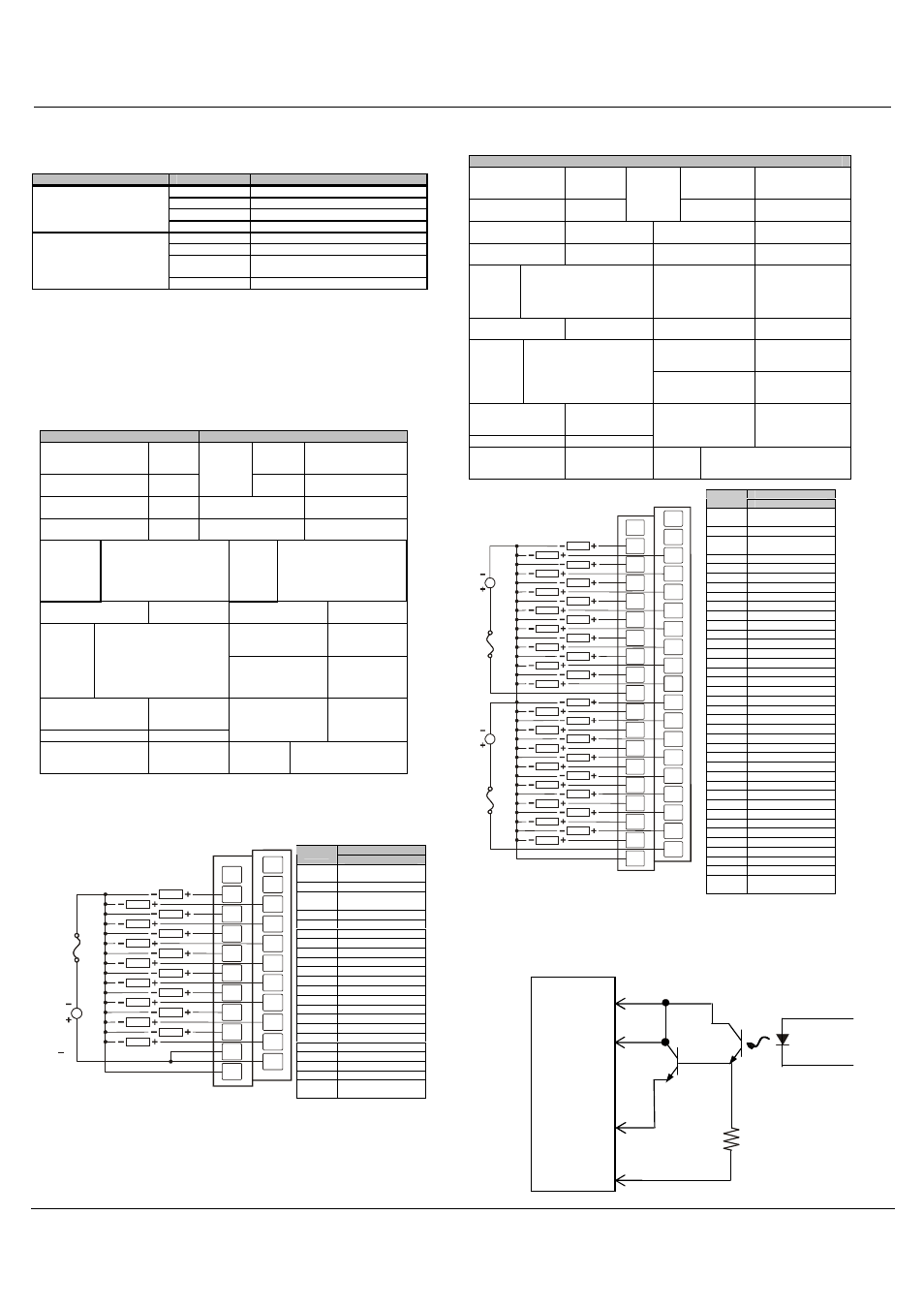
INTERNAL WIRING
a. DQM606
Signal
Pin
DQM606
NC*
No Connection
(*Do not Connect)
FG
Frame Ground
NC*
No Connection
(*Do not Connect)
Q1
Output 1
Q2
Output 2
Q3
Output 3
Q4
Output 4
Q5
Output 5
Q6
Output 6
Q7
Output 7
Q8
Output 8
Q9
Output 9
Q10
Output 10
Q11
Output 11
Q12
Output 12
Q13
Output 13
Q14
Output 14
Q15
Output 15
Q16
Output 16
COM
Isolated Common
COM
Isolated Common
0V
Isolated Power
Negative
COM
NC
FG
NC
0V
Q3
Q4
Q5
Q6
Q9
Q10
Q11
Q12
Q13
Q14
Q7
Q8
Q15
Q16
Q2
Q1
LOAD
24VDC
LOAD
LOAD
LOAD
LOAD
LOAD
LOAD
LOAD
LOAD
LOAD
LOAD
LOAD
LOAD
LOAD
LOAD
LOAD
COM
006DQM007-R1
Signal
Pin
DQM706
NC*
No Connection
(*Do not Connect)
FG*
Frame Ground
NC*
No Connection
(*Do not Connect)
Q1
Output 1
Q2
Output 2
Q3
Output 3
Q4
Output 4
Q5
Output 5
Q6
Output 6
Q7
Output 7
Q8
Output 8
Q9
Output 9
Q10
Output 10
Q11
Output 11
Q12
Output 12
Q13
Output 13
Q14
Output 14
Q15
Output 15
Q16
Output 16
C1
Isolated Common 1
Q17
Output 17
Q18
Output 18
Q19
Output 19
Q20
Output 20
Q21
Output 21
Q22
Output 22
Q23
Output 23
Q24
Output 24
Q25
Output 25
Q26
Output 26
Q27
Output 27
Q28
Output 28
Q29
Output 29
Q30
Output 30
Q31
Output 31
Q32
Output 32
C2
Isolated Common 2
0V
Isolated Power
Negative
C2
0V
NC
Q3
Q4
Q5
Q6
Q9
Q10
C1
Q11
Q12
Q13
Q14
Q7
Q8
Q15
Q17
Q2
Q1
FG
NC
LOAD
24VDC
LOAD
LOAD
LOAD
LOAD
LOAD
LOAD
LOAD
LOAD
LOAD
LOAD
LOAD
LOAD
LOAD
LOAD
LOAD
LOAD
24VDC
LOAD
LOAD
LOAD
LOAD
LOAD
LOAD
LOAD
LOAD
LOAD
LOAD
LOAD
LOAD
LOAD
LOAD
LOAD
Q16
Q19
Q18
Q21
Q20
Q23
Q22
Q25
Q24
Q27
Q26
Q29
Q28
Q31
Q32
Q30
006DQM008-R2
Note: If desired, C1 and C2 can
use a single supply.
0V
COM
Field
Side
I/O Connector
Q16
Q1
SmartStix
From
Controller