Horner APG SmartStix HE559DIM710 User Manual
Page 2
MAN0895-01
Specifications / Installation
_________________________________________________________________________________________________________________
03/03/2009 Page 2 of 3 ECN # 952
5
LEDs
a. Diagnostic LED Indicators
Diagnostic LED
State
Meaning
Solid Red
RAM or ROM test failed
Blinking Red
I/O test failed
Blinking Green
Module is in power-up state
MS: (indicates fault status of
Module )
Solid Green
Module is running normally
Solid Red
Network Ack or Dup ID test failed
Blinking Red
Network ID test failed
Blinking Green
Module is in Life Expectancy default
state
NS: (indicates fault status of
Network)
Solid Green
Network is running normally
b. Status LED Indicators
The Power Status LED illuminates Red when power is applied to the module. There are
I/O Status LED indicators for each of the Digital I/O points, which illuminate Red when an
I/O point is ON.
6
WIRING
a. 16 DC IN, Positive Logic / Negative Logic
DIM610 Specifications
Number of input points
16
OFF to ON
Response
0 - 3ms. or less
Rated Input Current
7mA
ON to OFF
Response
0 - 3ms. or less
ON Voltage Level
19VDC or less
Common
Terminal
16 points / COM
OFF Voltage Level
6VDC or less
Operating
Indicator
LED turns on during
ON state of input
Input Characteristics
Bidirectional
Isolation Method
Photo Coupler
External
Connections
Terminal block
connector (M3 x 6
screws)
Rated Voltage
11 – 25 VDC
Altitude for
use
Up to 2,000m
Internal power
Consumption (mA)
200mA
Weight
5.6 oz. (159 g)
b. 32VDC IN, Positive Logic / Negative Logic
DIM710 INPUTS
Number of input
points
32
OFF to ON Response
0 - 3ms. or less
Rated Input Current
7mA
ON to OFF Response
0 - 3ms. or less
ON Voltage Level
19VDC or less
Common Terminal
16 points / COM
OFF Voltage Level
6VDC or less
Isolation Method
Photo Coupler
Operating Indicator
LED turns on
during ON state
of input
Input
Characteristics
Bidirectional
External Connections
Terminal block
connector (M3 x
6 screws)
Rated Voltage
11 – 25 VDC
Internal power
Consumption (mA)
300
Weight
8.36oz. (237 g)
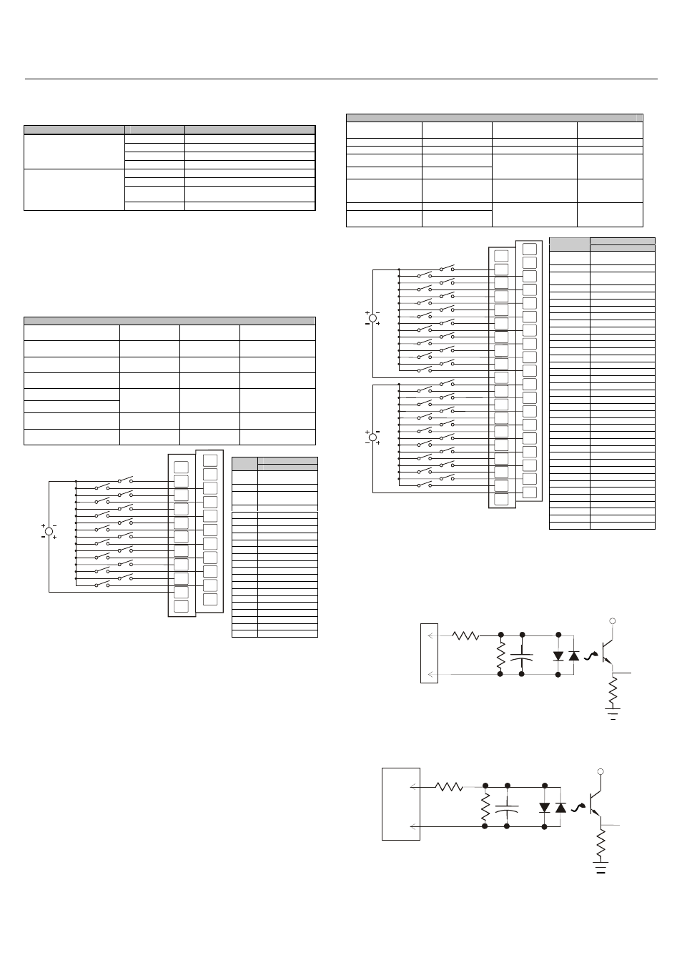
7
INTERNAL WIRING
a. DIM610
b. DIM710
Signal
Pin
DIM610
NC*
No Connection
(*Do not Connect)
FG
Frame Ground
NC*
No Connection
(*Do not Connect)
I1
Input 1
I2
Input 2
I3
Input 3
I4
Input 4
I5
Input 5
I6
Input 6
I7
Input 7
I8
Input 8
I9
Input 9
I10
Input 10
I11
Input 11
I12
Input 12
I13
Input 13
I14
Input 14
I15
Input 15
I16
Input 16
C
Common
C
Common
NC
No Connection
I1
I3
I4
I5
I6
I9
I10
C
24VDC
I11
I12
I13
I14
I7
I8
I15
I16
I2
C
NC
FG
006DIM005-R1
NC
NC
Signal
Pin
DIM710
NC*
No Connection
(*Do not Connect)
FG
Frame Ground
NC*
No Connection
(*Do not Connect)
I1
Input 1
I2
Input 2
I3
Input 3
I4
Input 4
I5
Input 5
I6
Input 6
I7
Input 7
I8
Input 8
I9
Input 9
I10
Input 10
I11
Input 11
I12
Input 12
I13
Input 13
I14
Input 14
I15
Input 15
I16
Input 16
C1
Isolated Common 1
I17
Input 17
I18
Input 18
I19
Input 19
I20
Input 20
I21
Input 21
I22
Input 22
I23
Input 23
I24
Input 24
I25
Input 25
I26
Input 26
I27
Input 27
I28
Input 28
I29
Input 29
I30
Input 30
I31
Input 31
I32
Input 32
C2
Isolated Common 2
NC
No Connection
I3
I4
I5
I6
I9
I10
C1
24VDC
I11
I12
I13
I14
I7
I8
I15
I16
C2
I2
I31
NC
I29
I30
I27
I28
I25
I26
I23
I24
I21
I22
I19
I20
I17
I18
24VDC
I1
I32
FG
006DIM006-R1
NC
NC
To
Controller
VCC
I/O Connector
C
I1
Field Side
SmartStix
To
Controller
VCC
I/O Connector
Isolated
C1
I1
Field
Side
SmartStix