Horner APG SmartStix HE559 User Manual
Page 2
MAN0519-10
_______
Specifications / Installation
_________________________________________________________________________________________________________________________________________________________________________________________________________
02/24/2009 Page 2 of 3
ECN # 952
c.
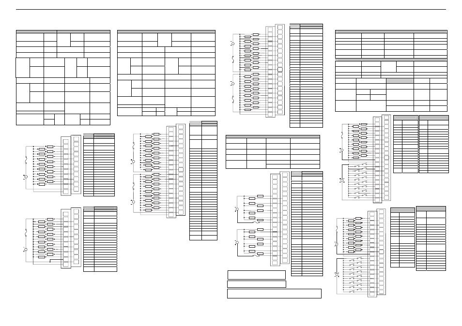
DQM601: 16 DC OUT, Negative Logic
DQM606: 16 DC OUT, Positive Logic
DQM601 / DQM606 Outputs
Number of output
points
16
Voltage
24VDC ± 10% (ripple
voltage: 4Vp-p or
less)
Commons per
Module
1
External
Power
Supply
Current
30mA (TYP, All
points ON)
Operating Voltage
24VDC
OFF to ON
Response
2ms.
Rated Load Voltage
24VDC
ON to OFF
Response
2ms.
DQM
601A
0.1A Max. per
output 2A per
common
DQM
601
Sinking
Max.
Load
Current
per
channel
•DQM
601B
•DQM
606
0.5A Max. per
output 3A per
common
Output
Type
DQM
606
Sourcing
OFF Leakage
Current
0.1mA or less
Common Method
16 points /
COM
DQM
601
0.4A, 10ms.
Operating
Indicator
LED turns on
during ON
state of output
Max.
Inrush
Current
per
channel
DQM
606
1A, 10ms
External
connections
Terminal block
connector
(M3 x 6
screws)
Maximum Voltage
Drop during ON
circuit
1.5VDC(0.5A)
Rated Voltage
11 – 25 VDC
Isolation methods
Photo Coupler
DQM
601
DQM
601
5.7 oz. (161g)
Internal power
Consumption (mA)
DQM
606
280
Weight
DQM
606
6.7 oz. (191g)
d.
DQM701: 32 DC OUT, Negative Logic
DQM706: 32 DC OUT, Positive Logic
DQM701 / 706 Outputs
Number of output
points
32
Voltage
24VDC ±
10%(ripple voltage:
4Vp-p or less)
Commons per
Module
2
External
Power
Supply
Current
30mA (TYP, All
points ON)
Operating Voltage
24VDC
OFF to ON
Response
2ms.
Rated Load
Voltage
24VDC
ON to OFF
Response
2ms.
DQM
701
0.1A Max. per
output 2A per
common
DQM
701
Sinking
Max.
Load
Current
per
channel
DQM
706
0.5A Max. per
output 3A per
common
Output
Type
DQM
706
Sourcing
OFF Leakage
Current
0.1mA or less
Common Method
16 points / COM
DQM
701
0.4A, 10ms.
Operating Indicator
LED turns on
during ON state of
output
Max.
Inrush
Current
per
channel
DQM
706
1A, 10ms
External
connections
Terminal block
connector
(M3 x 6 screws)
Maximum Voltage
Drop during ON
circuit
1.5VDC(0.5A)
Rated Voltage
11 – 25 VDC
Isolation methods
Photo Coupler
DQM701
340
DQM701
8.47 (240g)
Internal power
Consumption
(mA)
DQM706
380
Weight
DQM706
10.22 (290g)
e.
DQM602: 16 RELAY OUTPUTS
DQM602 Relay Outputs
Number of
output points
16
Minimum load
voltage / current
5VDC / 1mA
Commons per
Module
2
Maximum Load
Current (resistive)
2.0A per channel
5.0A per common
Rated Load
Voltage
24VDC,
220VAC
OFF to ON
Response
10ms. Max.
Rated Voltage
11 – 25 VDC
ON to OFF
Response
12ms. Max.
Output Type
N.O.
Internal power
Consumption
(mA)
550mA
Weight
9.91oz. (281 g)
f.
DIQ811: 16 DC IN, Positive/Negative / 16 DC OUT, Negative Logic
DIQ816: 16 DC IN, Positive / 16 DC OUT, Positive Logic
DIQ811 / 816 IN
Number of input
points
16
OFF to ON Response
0 - 3ms. or less
Rated Input Current
7mA
ON to OFF Response
0 - 3ms. or less
ON Voltage Level
19VDC or less
Common Terminal
16 points / COM
OFF Voltage Level
6VDC or less
Operating Indicator
LED turns on during ON
state of input
Input
Characteristics
Bidirectional
External Connections
Terminal block connector
(M3 x 6 screws)
Isolation Method
Photo Coupler
DIQ811 / 816 OUT
Number of output
points
16
Voltage
24VDC ± 10%(ripple
voltage: 4Vp-p or less)
Commons per
Module
1
External
Power
Supply
Current
30mA (TYP, All points ON)
Operating Voltage
24VDC
OFF to ON Response
2ms.
Rated Load Voltage
24VDC
ON to OFF Response
2ms.
OFF Leakage
Current
0.1mA or less
DIQ811
DIQ816
Rated Voltage
11 – 25 VDC
Max. Inrush Current
per channel
0.4A,
10ms.
1A, 10ms
DIQ811 DIQ816
Internal power
Consumption
(mA)
300 350
Max. Load Current
per channel
0.1A Max.
per output
2A per
common
0.5A Max.
per output
3A per
common
Output Type
Sinking
Sourcing
Common
Method
16 points / COM
Weight
8.40 oz.
(238 g)
10.16 oz.
(288 g)
Signal
Pin
DQM701
NC*
No
Connection
(*Do not
Connect)
FG
Frame
Ground
NC*
No
Connection
(*Do not
Connect)
Q1 Output
1
Q2 Output
2
Q3 Output
3
Q4 Output
4
Q5 Output
5
Q6 Output
6
Q7 Output
7
Q8 Output
8
Q9 Output
9
Q10 Output
10
Q11 Output
11
Q12 Output
12
Q13 Output
13
Q14 Output
14
Q15 Output
15
Q16 Output
16
C1
Isolated
Common 1
Q17 Output
17
Q18 Output
18
Q19 Output
19
Q20 Output
20
Q21 Output
21
Q22 Output
22
Q23 Output
23
Q24 Output
24
Q25 Output
25
Q26 Output
26
Q27 Output
27
Q28 Output
28
Q29 Output
29
Q30 Output
30
Q31 Output
31
Q32 Output
32
C2
Isolated
Common 2
V+
Isolator
Power
Warning: Connecting high voltage to any I/O pin may
cause high voltage to appear at other I/O pins.
Warning: To protect the module and associated wiring
from load faults, use external fuse (5 A) as shown.
Warning: Wiring the line side of the AC source to loads connected to outputs 0 through 15
and the neutral side of the AC source to the output common(s) would create a Negative
Logic condition, which may be considered an unsafe practice.
Signal
Pin
DQM602
NC*
No Connection
(*Do not Connect)
FG Frame
Ground
NC*
No Connection
(*Do not Connect)
NC No
Connection
NC No
Connection
NC No
Connection
NC No
Connection
NC No
Connection
NC No
Connection
Q1 Output
1
Q2 Output
2
C1 Common
1
Q3 Output
3
Q4 Output
4
C1
Common 1
Q5 Output
5
Q6 Output
6
C1
Common 1
Q7 Output
7
Q8 Output
8
C1
Common 1
NC No
Connection
C1
Common 1
Q9 Output
9
Q10 Output
10
C2 Common
2
Q11 Output
11
Q12 Output
12
C2 Common
2
Q13 Output
13
Q14 Output
14
C2
Common 3
Q15 Output
15
Q16 Output
16
C2 Common
2
NC No
Connection
C2 Common
2
NC No
Connection
C2
V+
NC
Q3
Q4
Q5
Q6
Q9
Q10
C1
Q11
Q12
Q13
Q14
Q7
Q8
Q15
Q17
Q2
Q1
FG
NC
LOAD
24VDC
LOAD
LOAD
LOAD
LOAD
LOAD
LOAD
LOAD
LOAD
LOAD
LOAD
LOAD
LOAD
LOAD
LOAD
LOAD
LOAD
24VDC
LOAD
LOAD
LOAD
LOAD
LOAD
LOAD
LOAD
LOAD
LOAD
LOAD
LOAD
LOAD
LOAD
LOAD
LOAD
Q16
Q19
Q18
Q21
Q20
Q23
Q22
Q25
Q24
Q27
Q26
Q29
Q28
Q31
Q30
R1
Q32
006DQM009-
FG
C1
Q3
Q8
Q4
C1
Q5
Q6
Q1
Q2
C1
Q7
C2
NC
C2
NC
C2
C2
C2
Q15
Q9
C1
NC
NC
NC
NC
NC
NC
NC
LOAD
220VAC
OR
24VDC
N
L
LOAD
LOAD
LOAD
LOAD
LOAD
LOAD
LOAD
LOAD
220VAC
OR
24VDC
N
L
LOAD
LOAD
LOAD
LOAD
LOAD
LOAD
LOAD
C1
Q14
Q11
Q10
Q16
Q13
Q12
006DQM008-R1
NC
NC
Signal
Pin
DQM606
NC*
No Connection
(*Do not Connect)
FG Frame
Ground
NC*
No Connection
(*Do not Connect)
Q1 Output
1
Q2 Output
2
Q3 Output
3
Q4 Output
4
Q5 Output
5
Q6 Output
6
Q7 Output
7
Q8 Output
8
Q9 Output
9
Q10 Output
10
Q11 Output
11
Q12 Output
12
Q13 Output
13
Q14 Output
14
Q15 Output
15
Q16 Output
16
COM Isolated
Common
COM
Isolated Common
0V
Isolated Power
Negative
COM
NC
FG
NC
0V
Q3
Q4
Q5
Q6
Q9
Q10
Q11
Q12
Q13
Q14
Q7
Q8
Q15
Q16
Q2
Q1
LOAD
24VDC
LOAD
LOAD
LOAD
LOAD
LOAD
LOAD
LOAD
LOAD
LOAD
LOAD
LOAD
LOAD
LOAD
LOAD
LOAD
COM
006DQM007-R1
Signal
Pin
DQM706
NC*
No Connection
(*Do not Connect)
FG* Frame
Ground
NC*
No Connection
(*Do not Connect)
Q1 Output
1
Q2 Output
2
Q3 Output
3
Q4 Output
4
Q5 Output
5
Q6 Output
6
Q7 Output
7
Q8 Output
8
Q9 Output
9
Q10 Output
10
Q11 Output
11
Q12 Output
12
Q13 Output
13
Q14 Output
14
Q15 Output
15
Q16 Output
16
C1
Isolated Common 1
Q17 Output
17
Q18 Output
18
Q19 Output
19
Q20 Output
20
Q21 Output
21
Q22 Output
22
Q23 Output
23
Q24 Output
24
Q25 Output
25
Q26 Output
26
Q27 Output
27
Q28 Output
28
Q29 Output
29
Q30 Output
30
Q31 Output
31
Q32 Output
32
C2
Isolated Common 2
0V
Isolated Power
Negative
Note: For proper operation, C1 and C2
must be tied together.
I3
I4
I5
I6
I9
I10
C2
I11
I12
I13
I14
I7
I8
I15
I16
I2
I1
0V
NC
Q3
Q4
Q5
Q6
Q9
Q10
C1
Q11
Q12
Q13
Q14
Q7
Q8
Q15
Q16
Q2
Q1
FG
NC
LOAD
24VDC
LOAD
LOAD
LOAD
LOAD
LOAD
LOAD
LOAD
LOAD
LOAD
LOAD
LOAD
LOAD
LOAD
LOAD
LOAD
24VDC
006DIQ004-R1
DIQ811
NC*
No Connection
(*Do not Connect)
NC*
No Connection
(*Do not connect)
Q2 Output
2
Q4 Output
4
Q6 Output
6
Q8 Output
8
Q10 Output
10
Q12 Output
12
Q14 Output
14
Q16 Output
16
V+
Isolator
Power
I2 Input
2
I4 Input
4
I6 Input
6
I8 Input
8
I10 Input
10
I12 Input
12
I14 Input
14
I16 Input
16
DIQ811
FG
Frame
Ground
Q1 Output
1
Q3 Output
3
Q5 Output
5
Q7 Output
7
Q9 Output
9
Q11 Output
11
Q13 Output
13
Q15 Output
15
C1
Isolated
Common
I1 Input
1
I3 Input
3
I5 Input
5
I7 Input
7
I9 Input
9
I11 Input
11
I13 Input
13
I15 Input
15
C2
Isolated
Common
DIQ816
NC*
No Connection
(*Do not
Connect)
NC*
No Connection
(*Do not
Connect)
Q2 Output
2
Q4 Output
4
Q6 Output
6
Q8 Output
8
Q10 Output
10
Q12 Output
12
Q14 Output
14
Q16 Output
16
0V
Isolated Ground
I2 Input
2
I4 Input
4
I6 Input
6
I8 Input
8
I10 Input
10
I12 Input
12
I14 Input
14
I16 Input
16
DIQ816
FG
Frame
Ground
Q1 Output
1
Q3 Output
3
Q5 Output
5
Q7 Output
7
Q9 Output
9
Q11 Output
11
Q13 Output
13
Q15 Output
15
C1
Isolated
Common
Power
I1 Input
1
I3 Input
3
I5 Input
5
I7 Input
7
I9 Input
9
I11 Input
11
I13 Input
13
I15 Input
15
C2
Isolated
Common
C2
0V
NC
Q3
Q4
Q5
Q6
Q9
Q10
C1
Q11
Q12
Q13
Q14
Q7
Q8
Q15
Q17
Q2
Q1
FG
NC
LOAD
24VDC
LOAD
LOAD
LOAD
LOAD
LOAD
LOAD
LOAD
LOAD
LOAD
LOAD
LOAD
LOAD
LOAD
LOAD
LOAD
LOAD
24VDC
LOAD
LOAD
LOAD
LOAD
LOAD
LOAD
LOAD
LOAD
LOAD
LOAD
LOAD
LOAD
LOAD
LOAD
LOAD
Q16
Q19
Q18
Q21
Q20
Q23
Q22
Q25
Q24
Q27
Q26
Q29
Q28
Q31
Q32
Q30
006DQM008-R2
Note: If desired, C1 and C2 can
use a single supply.
I3
I4
I5
I6
I9
I10
C2
I11
I12
I13
I14
I7
I8
I15
I16
I2
I1
V+
NC
Q3
Q4
Q5
Q6
Q9
Q10
C1
Q11
Q12
Q13
Q14
Q7
Q8
Q15
Q16
Q2
Q1
FG
NC
LOAD
24VDC
LOAD
LOAD
LOAD
LOAD
LOAD
LOAD
LOAD
LOAD
LOAD
LOAD
LOAD
LOAD
LOAD
LOAD
LOAD
24VDC
006DIQ003-R1
Signal
Pin
DQM601
NC*
No Connection
(*Do not Connect)
FG* Frame
Ground
NC*
No Connection
(*Do not Connect)
Q1 Output
1
Q2 Output
2
Q3 Output
3
Q4 Output
4
Q5 Output
5
Q6 Output
6
Q7 Output
7
Q8 Output
8
Q9 Output
9
Q10 Output
10
Q11 Output
11
Q12 Output
12
Q13 Output
13
Q14 Output
14
Q15 Output
15
Q16 Output
16
C Isolated
Common
C
Isolated Common
V+ Isolator
Power
C
NC
FG
NC
V+
Q3
Q4
Q5
Q6
Q9
Q10
Q11
Q12
Q13
Q14
Q7
Q8
Q15
Q16
Q2
Q1
LOAD
24VDC
LOAD
LOAD
LOAD
LOAD
LOAD
LOAD
LOAD
LOAD
LOAD
LOAD
LOAD
LOAD
LOAD
LOAD
LOAD
C
006DQM007-R1