2 wiring – Horner APG SmartStack I/O HE-DIQ712 User Manual
Page 2
PAGE 2
10 NOV 2006
MAN0316-08
DIQ712
Information is subject to change without notice. SmartStack is a trademark of Horner APG, LLC.
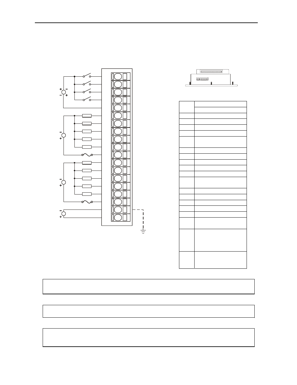
2 WIRING
2.1
Input / Output Connector Wiring
Warning:
To protect the module and associated wiring from load faults, use external fuse
(
10
A
)
as shown. This warning affects DIQ712, Revisions C or higher.
Warning:
Connecting high voltage to any I/O pin may cause high voltage to appear at other I/O
pins.
Warning:
Wiring the line side of the AC source to loads connected to outputs 1 through 10 and
the neutral side of the AC source to the output common(s) would create a Negative Logic
condition, which may be considered an unsafe practice.
Signal
Pin
DIQ712
I1 Input
1
I2 Input
2
I3 Input
3
I4 Input
4
C1
Common for
Inputs1,2,3,4
Q1 Output
1
Q2 Output
2
Q3 Output
3
Q4 Output
4
Q5
Output 5
C2 Common
for
Outputs
1,2,3,4,5
Q6 Output
6
Q7 Output
7
Q8 Output
8
Q9 Output
9
Q10 Output
10
C3 Common
for
Outputs
6,7,8,9,10
VC
Relay Coil power
common, connected
to bus common
internally.
V+
Relay Coil Power,
+18 to +30VDC,
90mA max.
*
OCS Bottom View – Shows
Corresponding I/O Pin
*
LOAD
I1
I2
I3
I4
Q3
C2
V+
Q5
C3
VC
Q1
Q2
C1
Q4
LOAD
LOAD
LOAD
LOAD
LOAD
LOAD
LOAD
LOAD
LOAD
Q9
Q8
Q7
Q6
Q10
C3
Q9
Q10
12-24VDC
18-30VDC
001DIQ009-R2
5-250VAC
OR
5-30VDC
N
L
5-250VAC
OR
5-30VDC
N
L