4configuration, 4 configuration – Horner APG RCX HE500RCX404 User Manual
Page 5
MAN0504-02
23 MAY 2003
PAGE 5
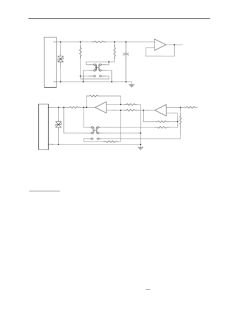
OCX404
Mini Analog Input
I/O Connector
To
Controller
±20mA
±10V
C
I1
3
2
1
6
4
5
806K
200K
12V
1nF
-
+
100
Field
Side
I/O Connector
Field
Side
Mini Analog Output
±20mA
±10V
From
Controller
C
Q1
100
-
+
12V
-
+
3
2
1
6
4
5
Specification for transient voltage suppressors (transorbs) used on output circuitry is 12VDC, 600 watts.
4 CONFIGURATION
Note: The status of the I/O can be monitored in Cscape Software.
Module Setup Tab
The Module Setup is used to configure the Analog
Inputs and Analog Outputs ±10V and ±20mA modes
and for applications where it is necessary to change the
default states or values of the outputs when the
controller (e.g., OCS100) enters idle/stop mode.
1. For Digital Outputs: The default turns the outputs
OFF when the controller enters idle/stop mode. By
selecting the Module Setup tab, each output can be set
to either turn ON, turn OFF or to hold the last state.
Generally, most applications use the default settings.
Warning: The default turns the digital outputs OFF
when the controller enters idle/stop mode. To avoid
injury of personnel or damages to equipment,
exercise extreme caution when changing the default
settings.
2. For Analog Outputs:
Mode: ±10V or ±20mA must be set for each channel. The
associated slide switch on the back of the module must
match the Cscape setting for each channel.
Idle: The default sets the output values to zero when the
controller enters idle/stop mode. By selecting the Module
Setup tab, each output can be set to a specific value or hold
the last value. Generally, most applications use the default
settings.
Warning: The default sets the output values to zero
when the controller enters idle/stop mode. To avoid
injury of personnel or damages to equipment, exercise
extreme caution when changing the default setting using
the Module Setup tab.
3. For Analog Inputs: :
Mode: ±10V or ±20mA must be set for each channel. The
associated slide switch on the back of the module must
match the Cscape setting for each channel.
Filter Constant: Sets the level of digital filtering according to
the following chart.
I/O Map Tab
The I/O Map describes which I/O registers are assigned.
The I/O Map is not edited by the user.
Information is subject to change without notice. Cscape is a trademark of Horner APG, LLC.