Horner APG XLt OCS HEXT240C012 User Manual
Page 3
MAN0869-06-EN
Specifications / Installation
__________________________________________________________________________________________________________________________________________________________________
12/17/2008
Page 3 of 4 ECN # 947
5
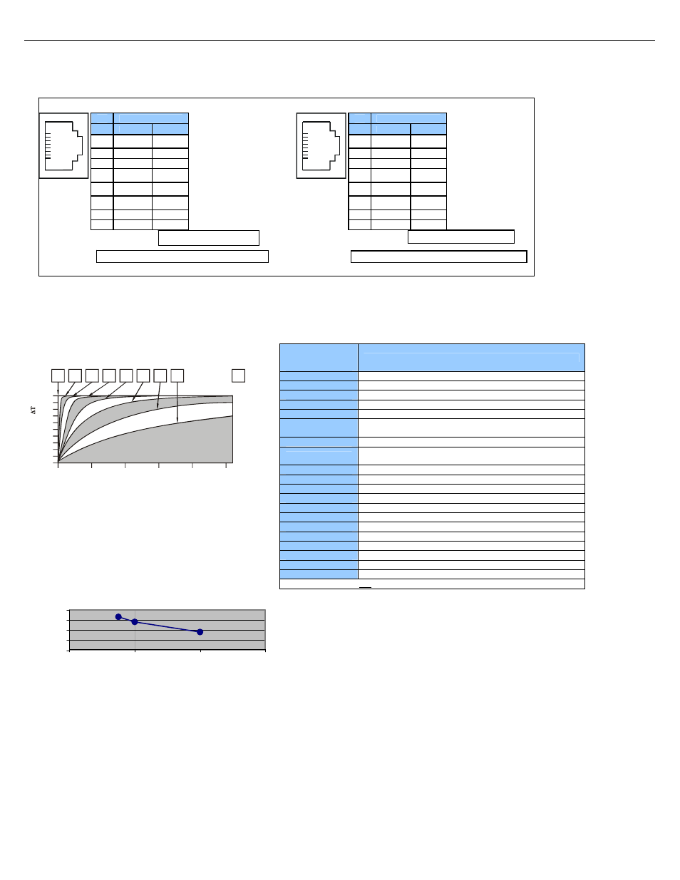
MJ2 Pinouts in Full and Half Duplex Modes
6
Filter
Filter Constant sets the level of digital filtering according to the
following chart.
Digital Filtering. The illustration above demonstrates the effect of
digital filtering (set with Filter Constant) on module
response to a temperature change.
7
Derating
Pin
MJ2 Pins
Signal
Direction
8
TXD OUT
7
RXD IN
6
0 V
Ground
5*
+5 60mA
OUT
4
TX- OUT
3
TX+ OUT
2
RX- IN
1
RX+ IN
1
8
* +5Vdc 60mA Max
MJ2 Full Duplex Mode
MJ2 Half Duplex Mode
Pin
MJ2 Pins
Signal
Direction
8
TXD OUT
7
RXD IN
6
0 V
Ground
5*
+5 60mA
OUT
4
TX- OUT
3
TX+ OUT
2
TX-/RX- IN/OUT
1
TX+/RX+ IN/OUT
1
8
* +5Vdc 60mA Max
8 I/O
Register
Map
Registers
Description
60
20
100
40
80
20
0
10
100
90
80
70
60
50
40
30
Scans
0
1
2
3
4
5
6
0
7
%
C
o
m
p
let
e
[
]
Filter
Constant
%I1 to %I24
Digital Inputs
%I32 Output
Fault
%I25 to %I31
Reserved
%Q1 to %Q16
Digital outputs
%Q17
Clear HSC1 accumulator to 0
Totalizer: Clear HSC2
%Q18
Quadrature 1-2: Accumulator 1 Reset to max – 1
%Q19
Clear HSC3 Accumulator to 0
Totalizer: Clear HSC4
%Q20
Quadrature 3-4: Accumulator 3 Reset to max – 1
%Q21 to %Q32
Reserved
%AI1 to %AI4
Analog inputs
%AI5, %AI6
HSC1 Accumulator
%AI7, %AI8
HSC2 Accumulator
%AI9, %AI10
HSC3 Accumulator
%AI11, %AI12
HSC4 Accumulator
%AQ1, %AQ2
PWM1 Duty Cycle
%AQ3, %AQ4
PWM2 Duty Cycle
%AQ5, %AQ6
PWM Prescale
%AQ7, %AQ8
PWM Period
%AQ9 to %AQ14
Analog outputs
Note: Not all XLt units contain the I/O listed in this table.
Relay Life Expectancy
0
10
20
30
40
1
2
3
4
Contact Current (A)
O
p
er
at
ion
(x10
4
)