4 serial communications, 5 dip switches, wiring and jumpers, 6 derating – Horner APG XLt OCS HE-XT102-14 User Manual
Page 2
MAN0867-01-EN
Specifications / Installation
__________________________________________________________________________________________________________________________________________________________________
3/26/2009 Page 2 of 4 ECN # 956
4
Serial Communications:
5
DIP Switches, Wiring and Jumpers
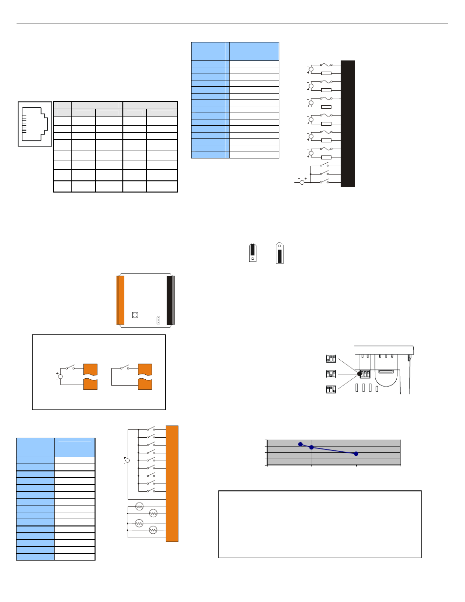
Wire according to the type of inputs / outputs used, and select the
appropriate jumper option.
5.1. Wiring
Examples
J1 Orange
Terminal
Connector
XT102
Name
I1 IN1
I2 IN2
I3 IN3
I4 IN4
I5 IN5
I6 IN6
I7 IN7
I8 IN8
H1 HSC1
/IN9
0V Ground
A1 Thermistor
1
A2 Thermistor
2
A3 Thermistor
3
A4 Thermistor
4
0V Ground
J2 Black
Terminal
Connector
XT102-10
Name
C6
Relay 6 COM
R6
Relay 6 NO
C5
Relay 5 COM
R5
Relay 5 NO
C4
Relay 4 COM
R4
Relay 4 NO
C3
Relay 3 COM
R3
Relay 3 NO
C2
Relay 2 COM
R2
Relay 2 NO
C1
Relay 1 COM
R1
Relay 1 NO
H4
HSC4 / IN12
H3
HSC3 / IN11
H2
HSC2 / IN10
5.2
I/O Jumpers Settings (JP1)
5.3
DIP Switch Settings
6 Derating
Note:
The Cscape Module Setup configuration must match the selected I/O (JP) jumper settings.
001XLE026
JP1 Digital DC In / HSC
Positive Negative
Logic Logic
Default
Location of I/O jumpers (JP)
and wiring connectors
(J1 and J2).
I1
0V
001XLE036
12-24VDC
I1
0V
Positive Logic In Negative Logic In
Positive Logic vs. Negative Logic Wiring
The XLT can be wired for Positive Logic inputs or
Negative Logic inputs.
001XLE015
0V ON J1
12-24VDC
R2
C2
R3
C3
R6
C6
R4
C4
R5
C5
R1
C1
H4
H2
H3
LOAD
230VAC
OR
25VDC
N
L
LOAD
230VAC
OR
25VDC
N
L
LOAD
230VAC
OR
25VDC
N
L
LOAD
230VAC
OR
25VDC
N
L
LOAD
230VAC
OR
25VDC
N
L
LOAD
230VAC
OR
25VDC
N
L
XT102-10 J2 Black
Positive Logic
Digital In / Relay Out
Serial Communications:
MJ1
: (RS-232 / RS-485) Use for Cscape programming and
Application-Defined Communications.
MJ2:
(RS-232 / RS-485) Use for Application-Defined
Communications.
Pin
MJ1 Pins
MJ2 Pins
Wiring Specifications
For I/O wiring (discrete), use the
following wire type or equivalent:
Belden 9918, 18 AWG or larger.
For shielded Analog I/O wiring,
use the following wire type or
equivalent: Belden 8441, 18
AWG or larger.
For CAN wiring, use the
following wire type or equivalent:
Belden 3084, 24 AWG or larger.
The DIP Switches are used for
termination of the RS-485 ports.
The XLE is shipped un-terminated.
To terminate, select one of the
DIP switches and configure it
based upon the option that is
desired.
Factory Use
(default – none)
MJ2 Termination
(default – none)
MJ1 Termination
(default – none)
As seen when looking at the top of the XLT unit:
XT102 J1 Orange
Positive Logic In
Digital In /
Analog In
XLT102 Relay Life Expectancy
0
10
20
30
40
1
2
3
4
Contact Current (A)
Operati
on
(x10
4
)
Signal
Direction
Signal
Direction
1
8
8
TXD OUT TXD OUT
7
RXD IN RXD IN
6
0 V
Ground
0 V
Ground
5
+5
(60mA)
OUT
+5
(60mA)
OUT
4
RTS OUT TX- OUT
3
CTS IN TX+ OUT
2
RX- /
TX-
IN / OUT
RX-
IN
1
RX+ /
TX+
IN / OUT
RX+
IN
J1
JP2
JP1
J2
001XLE062
001XLE037-R1
I1
I2
I3
I4
0V
A1
A2
0V
I5
I6
I7
I8
A3
A4
H1
001XLE067
12-24VDC
T
T
T
T
WARNING
: EXPOSURE TO SOME CHEMICALS MAY DEGRADE
THE SEALING PROPERTIES OF MATERIALS USED IN THE Tyco relay PCJ
Cover / case & base: Mitsubishi engineering Plastics Corp.
5010GN6-30 or 5010GN6-30 M8 (PBT)
Sealing Material: Kishimoto 4616-50K (I part epoxy resin)
It is recommended to periodically inspect the relay for any
degradation of properties and replace if degradation is found