Aalborg TIO Totalizer I/O Flow Monitor/Controller User Manual
Page 59
56
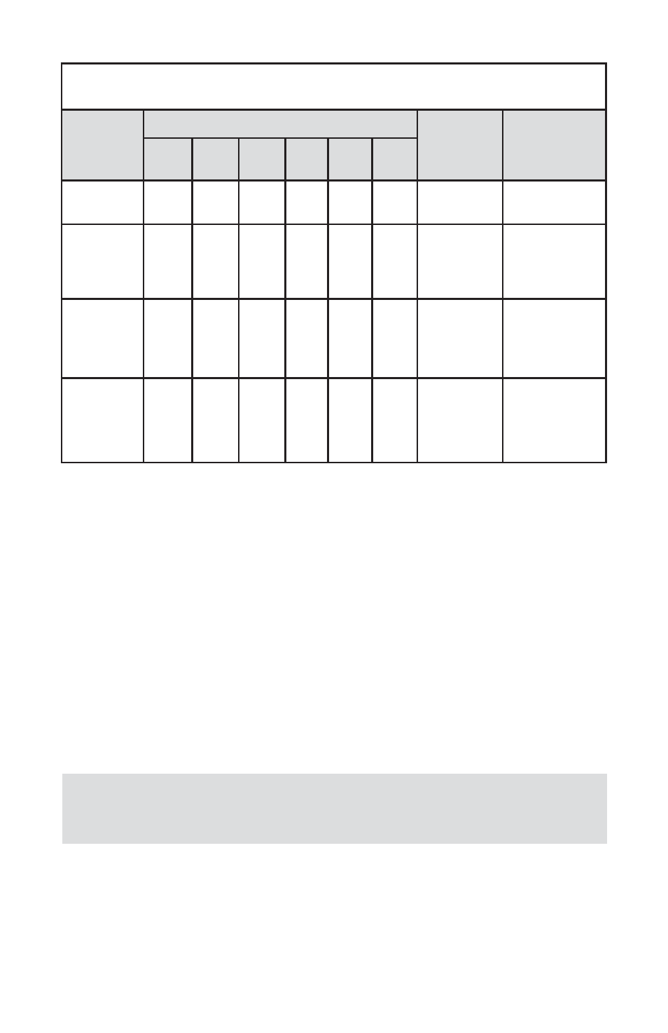
TABLE 6.2 J2 INPUT / OUTPUT JUMPER CONFIGURATION OPTIONS
FOR GFM SERIES FLOW METERS
PV INPUT
TYPE
(TIO INPUT)
J2 JUMPER CONFIGURATION
GFM
CABLE KIT
NOTE
J2A
J2B
J2C
J2D
J2E
J2F
0 - 5 Vdc
2 - 3
5 - 6
8 - 9 10-11 14-15 17-18
KIT-TM-DD
KIT-TM-FD
5 - 10 Vdc
2 - 3
5 - 6
8 - 9 11-12 14-15 17-18 KIT-TM-RD
+5Vdc
reference
signal must
be used
0 - 10 Vdc
2 - 3
5 - 6
8 - 9 11-12 14-15 17-18
NOT
SUPPORTED
FOR GFM
Special Order
option! (PCB
hardware must
be changed)
4 – 20 mA
2 - 3
5 - 6
8 - 9 10-11 13-14 16-17
N/A (user
custom cable
assembly)
(249 Ohm
passive, not
isolated current
input)
d) Parameters Configuration
Following parameters must be configured:
• Device Function (See 4.3.12 Submenu “Device Function”). “Meter”
function must be selected.
• Full Scale Range (See 4.3.14 Submenu “Device Calibration”). Full
Scale Range parameter must be set equal to the GFM full scale flow
rate in Litr/min.
• Fluid Std. Density (See 4.3.14 Submenu “Device Calibration”). This
parameter is required only when mass-based engineering units are
selected.
User may configure other parameters (see Paragraph 5.3) according
to individual preferences and application requirements.
NOTE: If “Full Scale Range”, “Device Function” and “Fluid Std.
Density” parameters are not set properly the device may have
erroneous reading and unpredictable behavior.
,