Aalborg TIO Totalizer I/O Flow Monitor/Controller User Manual
Page 58
55
Based on interface being used, Optional Cables Kit Assemblies are available for
order. See Table 6.1 for optional GFM cables kit assemblies.
c) Input/Output Jumper Configuration
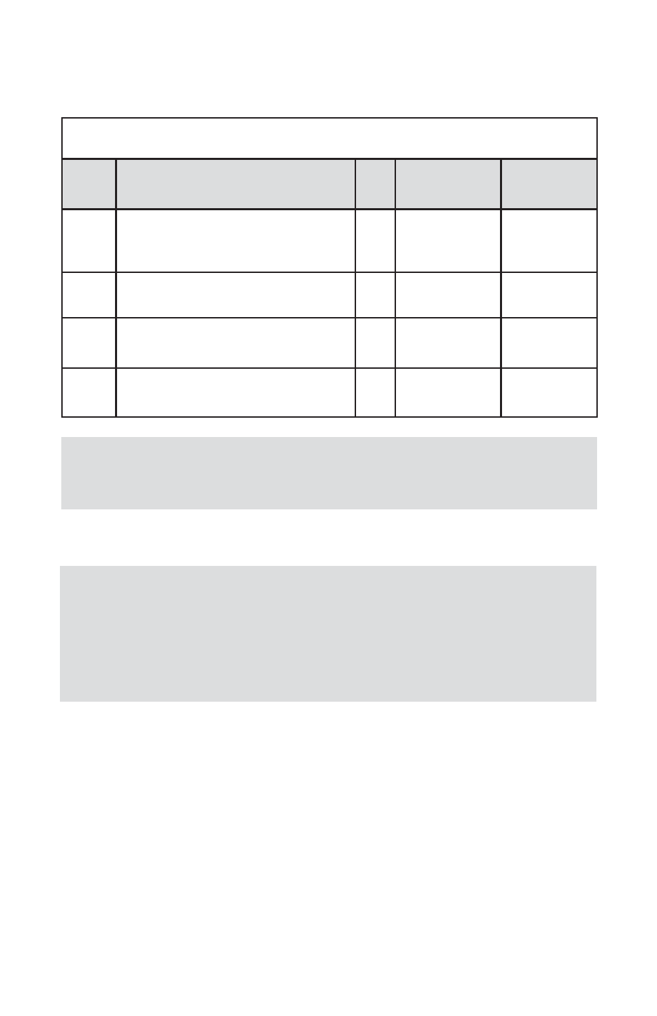
TABLE 6.1 OPTIONAL GFM CABLES AND MOUNTING KIT ASSEMBLIES
Kit Part
Number
DESCRIPTION
TIO
Input
Communication
Interface Cable
GFM Power
Supply Option
KIT-TM-
DD
Shielded cable with two 9 pins D-con-
nectors for process signals and 6 feet
communication branch
0-5
Vdc
YES
12 and 24 Vdc
KIT-TM-
RD
4 wires cable between GFM RJ11 and
TIO 9 pin D-connector
5-10
Vdc
NO
12 Vdc only
KIT-TM-
FD
Flat 4 wires cable between GFM and
TIO 9 pin D-connectors
0-5
Vdc
NO
12 and 24 Vdc
KIT-TM
GFM flow meter mounting kit,
no cables
N/A
N/A
N/A
NOTE: For all GFM Kits (except KIT-TM) it is assumed that the power
supplied is connected to the GFM power DC jack connector and the
TIO receiving the power from the GFM.
,
NOTE: Your TIO device input / output jumpers were configured at
the factory according to your order. There is no need to change input
/ output jumpers’ configuration unless a different input is being
used. Before applying power and process signals, make sure the
input /output jumpers are installed in the correct position
(See Table 6.2).
,