Aalborg TIO Totalizer I/O Flow Monitor/Controller User Manual
Page 11
7
4.3
Set Point (SP) Output Signal Connections
Set Point (SP) output signal connection is required only if TIO is mated to the
flow controller and will be used as a source for a Set Point control signal.
Depending on the jumper J2 configuration, SP output signal can be set to 0-5,
0-10 Vdc or 4-20 mA.
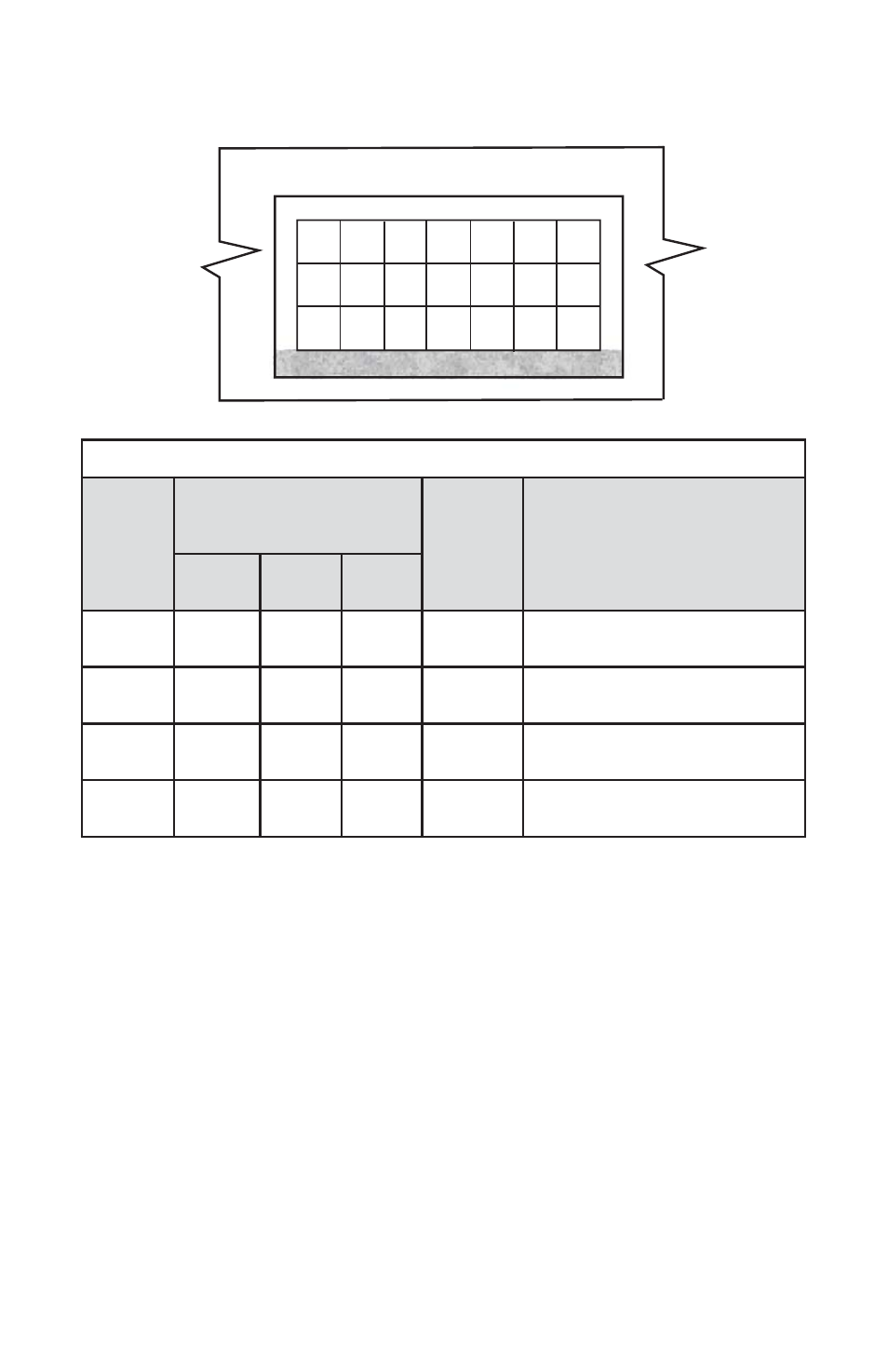
Table 4.1 Maximum rated values for PV input signals
PV
INPUT
TYPE
J2 JUMPER
CONFIGURATION
MAXIMUM
SIGNAL
LEVEL
NOTE
J2D
J2E
J2F
0-5 Vdc
10 -11
14 -15
17-18
≤6 Vdc
5-10 Vdc
11 -12
14 -15
17-18
≤11 Vdc
+5Vdc reference signal
must be used (GFM/GFC option)
0-10 Vdc
11 -12
14 -15
17-18
≤11 Vdc
Special Order option! (PCB
hardware must be changed)
4-20 mA
10 -11
13 -14
16-17
≤25 mA
(249 Ohm passive, not isolated
current input)
3
2
1
6
5
4
9
8
7
12
11
10
15
14
13
18
17
16
21
20
19
A
B
C
D
E
F
G
Figure 4.2 - TIO Input/Output Configuration Jumpers
PV input (+) --------------- pin 4 of the 9 pin “D” connector.
PV input (-) --------------- pin 8 of the 9 pin “D” connector.