1 telemetry line connections, 2 alarm contact and relay connections – Videotec ULISSE MAXI User Manual
Page 23
EN - English - I
nstruc
tions manual
21
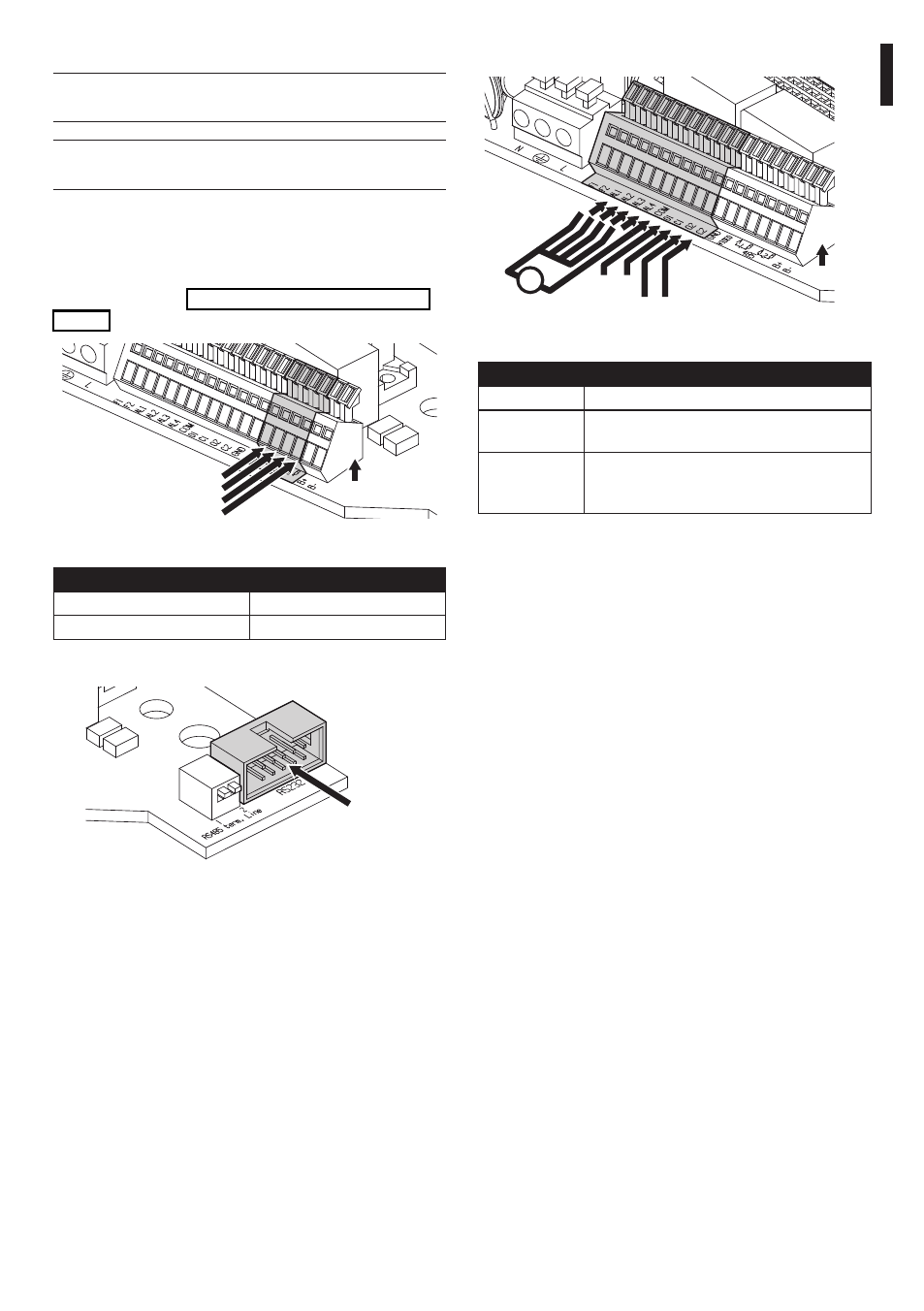
7.2.4.2 Alarm contact and relay connections
Signal
Vdc
O1 C1
O2 C2
+
V
Fig. 38
TERMINALS
DESCRIPTION
F1-F2
Additional lines
O1-C1 and
O2-C2
Clean output contacts, can be activated by
alarm or by user control
AL1, AL2, AL3,
AL4 and COM
Live controlled alarm inputs referring to
common COM
Tab. 07
7.2.4.1 Telemetry line connections
h
The installation is type TNV-1, do not
connect it to SELV circuits.
h
In order to reduce the risk of fire, only use
cable sizes greater than or equal to 26AWG.
The product is supplied with 2 RS485 serial
communication lines and 1 RS232 serial line. These
can be configured in various ways according to the
positions of dip-switches 10 and 9 on the Serial and
Address selector ("7.4.5 Serial communication lines",
page 25).
A1
B1
A2
B2
Signal
Fig. 36
TERMINALS
DESCRIPTION
A1-B1
Line RS485 (1)
A2-B2
Line RS485 (2)
Tab. 06
RS232
Fig. 37