2 connector for camera/motorised lenses – Videotec ULISSE MAXI User Manual
Page 18
EN - English - I
nstruc
tions manual
16
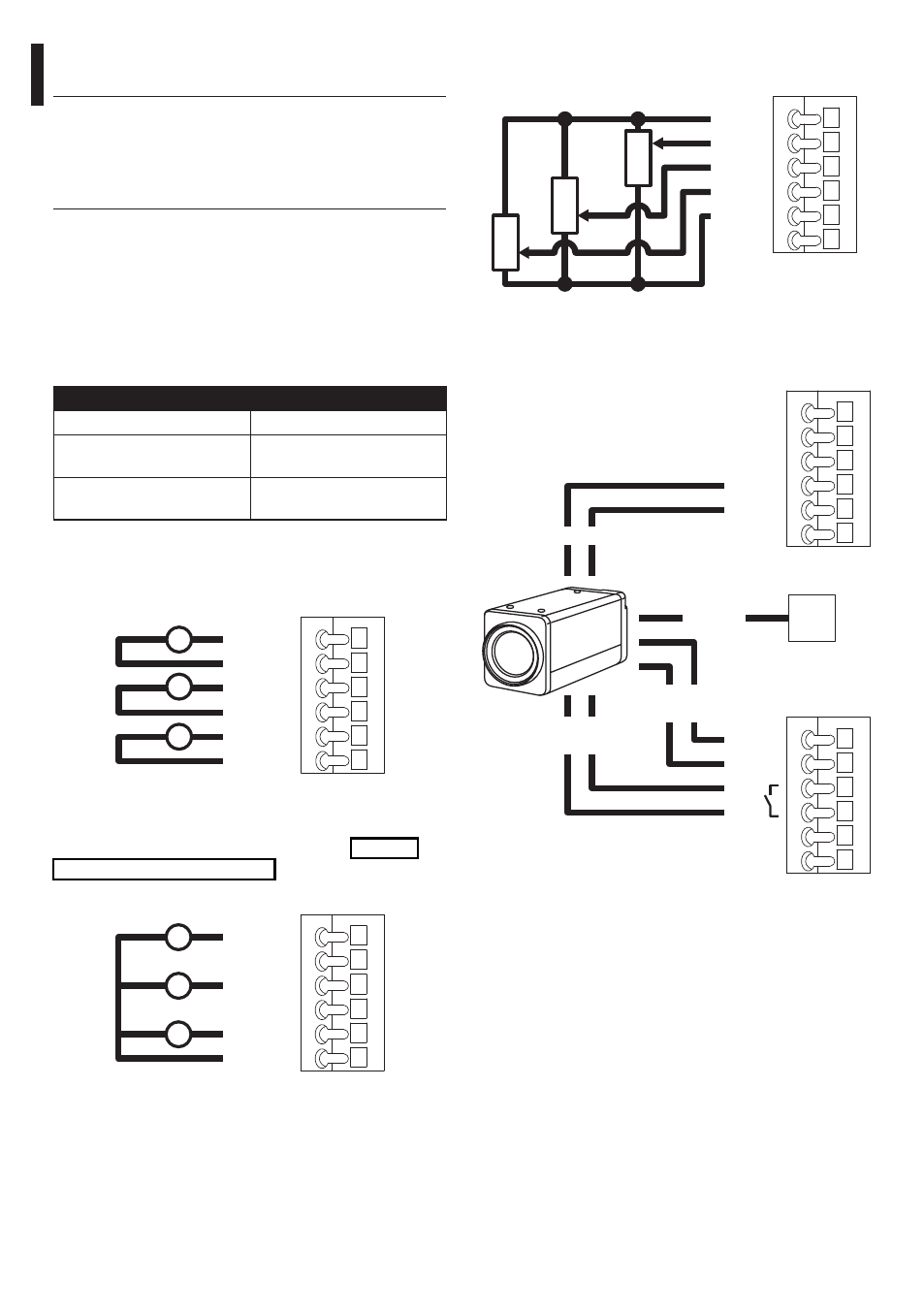
The potentiometer connections must be made as
shown in the following diagram.
+ POT
FOCUS
IRIS
ZOOM
- POT
GND
CN3
IRIS
ZOOM
FOCUS
Fig. 22
The camera connections must be made as shown in
the following diagram.
CN6
CN1
232 TX
232 RX
GND
485_B
485_A
S_GND
+ 12V
GND
F1
F2
Video
Night
synchronization
Serial
Power
supply
CN1
Fig. 23
Refer to the relative chapter to enable camera control
("9.6.4 Housing Serial Port Menu", page 34)
7.1.2.2 Connector for camera/motorised
lenses
h
All connections illustrated below should
be made only and exclusively by expert
installers who should comply with all the
wiring and power supply specifications for
the devices.
The electronics board is designed to control cameras
with motorised lenses (Focus, Iris, Zoom), which
may or may not have potentiometers to control the
position reached.
Before making the connections make sure that the
voltages supplied by the board fall within the limits
allowed for the apparatus.
CONNECTOR FOR CAMERA/MOTORISED LENSES
Camera power supply
+12V - 800mA max
Lens potentiometer power
supply
+5V - 15mA max
Lens motor power supply
6-15V (adjustable) - 200mA
max (Focus+ Zoom+Iris)
Tab. 02
In the case of lenses with reverse polarity motors,
connect as shown in the following drawing:
FOCUS +
FOCUS -
IRIS +
IRIS -
ZOOM +
ZOOM -
+
M
+
M
+
M
Fig. 20
CN2.
In the case of lenses with common wire motors,
enable the corresponding menu option ("9.6.3 ZFI
camera settings menu", page 32) and connect as
shown in the following drawing:
FOCUS +
FOCUS -
IRIS +
IRIS -
ZOOM +
ZOOM -
+
M
+
M
+
M
Fig. 21
CN2.