Powerline user guide – High Country Tek PLD, Powerline / universal single / dual coil PWM Valve Driver User Manual
Page 25
Part No:-
021-00155 RevD7
PowerLine System Controller User Guide
Page | 25
PowerLine User Guide
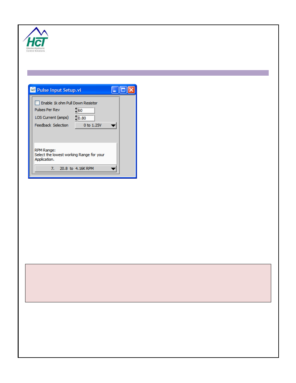
Pulse Input Setup:
Selection from Menu-> Pulse Input Setup
Enable Pull Down Resistor
This check box is used to enable a 10k resistor from the
pulse input to ground for use on systems with open emitter
sensors.
Pulses Per Rev
Number of pulses per revolution
LOS Current (amps) – (Loss Of Signal Current)
The user can set the coil current to drive when a loss of
signal is detected.
Feedback Selection
Used to select a voltage range for the Pulse Input. Pulses
must cross the midpoint of the range selected to be
detected and may exceed the range without damage to the
unit if less than +/- 30-Volts.
RPM Range
Use to select the best range for the application. If more than one range works, select the lowest range that fits
your application.
Configuration Steps:
1. Enter the number of teeth or pulses per revolution (maximum 255)
2. Enter LOS (Loss Of Signal) Current
3. Select voltage range of the pulse input under Feedback Selection
4. Select a RPM range that best fits the application; choose the range with the highest “lower” RPM
value that will work.
Application Tips
Inductive Pickup - Use 1 to -1v for Feedback Selection value
Hall Effect Pickup - Use 0 – 5v, or 0 – 10v for Feedback Selection value