2 module 2 - s, 0 hi-t, No lo-en – Red Lion CUB5TC User Manual
Page 8: No fcs, 0 lo-t, No hi-en, 48 code, 66 code, Econdary, Unction
8
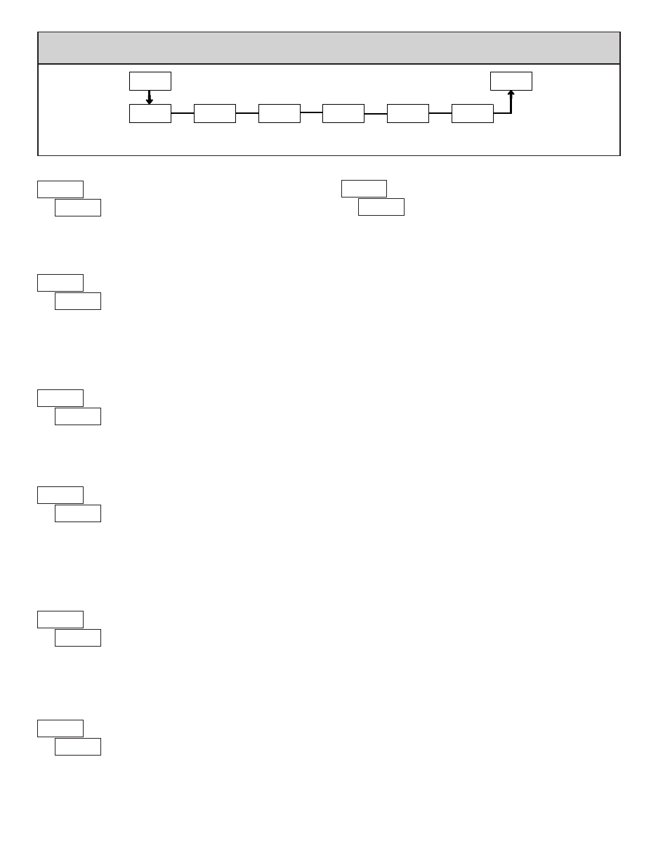
5.2 Module 2 - S
econdary
f
unction
p
araMeterS
(
2-SEC
)
SEL
Max Capture
Delay Time
Max Display
Enable
Min Display
Enable
Access Code
For Service
Operations
Min Capture
Delay TIme
Factory
Service
Operations
2-SEC
HI-En
HI-t
LO-En
LO-t
FCS
CodE
Pro
PARAMETER MENU
MIN DISPLAY ENABLE
YES
NO
2.0
HI-t
NO
LO-En
NO
FCS
MAX CAPTURE DELAY TIME
When the Input Display is above the present MAX value for the entered
delay time, the meter will capture that display value as the new MAX reading.
A delay time helps to avoid false captures of sudden short spikes.
2.0
LO-t
MIN CAPTURE DELAY TIME
When the Input Display is below the present MIN value for the entered delay
time, the meter will capture that display value as the new MIN reading. A delay
time helps to avoid false captures of sudden short spikes.
0.0
to
999.9
seconds
NO
HI-En
MAX DISPLAY ENABLE
0.0
to
999.9
seconds
Select
YES
to perform either of the Factory Service Operations shown below.
FACTORY SERVICE OPERATIONS
yES
NO
YES
NO
Enables the Maximum Display Capture capability.
Enables the Minimum Display Capture capability.
The CUB5TC uses stored voltage calibration and cold
junction temperature values to provide accurate temperature
and voltage measurements. Over time, the electrical
characteristics of the components inside the meter could
slowly change. The result is that the stored calibration values may no longer
accurately define the input circuit. For most applications, recalibration every 1
to 2 years should be sufficient.
Calibration of the CUB5TC involves a voltage calibration and a cold
junction calibration. It is recommended that both calibrations be performed.
The voltage calibration MUST precede the cold junction calibration. Allow 30
minute warm up before performing any calibration related procedure. The
following procedures should be performed at an ambient temperature of 15 to
35 °C (59 to 95 °F).
Calibration should only be performed by individuals experienced in
calibrating electronic equipment.
CAUTION: The accuracy of the calibration equipment will directly affect the
accuracy of the CUB5TC.
Input Voltage Calibration
1. Connect a precision DC voltage source with an accuracy of 0.01% or better
to the TC+ (positive) and the TC- (negative) terminals of the CUB5TC. Set
the output of the voltage source to zero.
2. With the display at
CodE 48
, press and hold the
SEL
button for 2 seconds. Unit
will display
CAL NO
.
3. Press the
RST
button to select
INP
.
4. Press the
SEL
button. Display reads
0.0u
.
5. With the voltage source set to zero, press
SEL
. Display reads
CALC
for about
eight seconds.
6. When display reads
60.0u
, apply 60.000 mV input signal. Press
SEL
. Display
reads
CALC
for about eight seconds.
7. When display reads
CAL NO
, press
SEL
twice to exit Module 2 and return to
the normal display mode.
8. Proceed to Cold Junction Calibration.
Cold Junction Calibration
1. Install all option cards needed for your application and the rear cover,
or invalid results will occur.
2. The ambient temperature must be within 20°C to 30°C.
3. Connect a thermocouple (types T, E, J, K, or N only) with an accuracy of 1°C
or better to the meter.
4. Enter programming mode and verify the following settings in Module 1:
tYPE
= thermocouple type connected to the unit
CJC
=
YES
;
SCALE
=
°C
;
dECPt
=
0.0
;
OFSEt
=
0
5. Place the thermocouple in close thermal contact to a reference thermometer
probe. (Use a reference thermometer with an accuracy of 0.25°C or better.)
The two probes should be shielded from air movement and allowed sufficient
time to equalize in temperature. (A calibration bath of known temperature
could be used in place of the thermometer.)
6. Compare the unit display with the reference temperature indicator (or
calibration bath). If a difference of more than ±1.0 °C exists, note the
difference (CJ error) and continue with cold junction calibration.
CJ Error = Reference Temperature - Unit Display.
7. Enter programming mode. Step through Module 2 to the Service Access
Code parameter and select
CodE 48
. Press and hold the
SEL
button until the
unit displays
CAL NO
. Press the
RST
button to select
CJC
.
8. Press
SEL
. Display reads
CJC
followed by the current cold junction value.
Calculate a new cold junction value as follows:
New cold junction = Current cold junction + CJ Error (noted above)
9. Press
RST
and set the display to the new cold junction value. Press and hold
SEL
. Display reads
CALC
for about four seconds and then returns to
CAL NO
.
10. Press
SEL
twice to exit calibration and return to the normal display mode.
Verify the input reading is correct. If not, repeat steps 6 through 10.
CALIBRATION
48
CodE
RESTORE FACTORY DEFAULT SETTINGS
Entering Code 66 will overwrite all user settings with
the factory settings. The meter will display
rESEt
and then
return to
CodE 00
. Press
SEL button to exit the module.
Pressing both the
SEL and the RST button on power-up
will also load the factory settings and display
rESEt
. This allows operation in
the event of a memory failure or corruted data.
66
CodE