Eviewing, Ront, Uttons – Red Lion CUB5TC User Manual
Page 6: Isplay, Rogramming, Eter, N0 usrin, Sec 1-inp 4-spt 5-ser, Overview, Programming menu
6
4.0 r
evieWinG
the
f
ront
B
uttonS
and
d
iSplay
SEL
RST
PROGRAMMING MODE ENTRY (SEL BUTTON)
It is recommended that all programming changes be made off line, or before
installation. The meter normally operates in the Display Mode. No parameters
can be programmed in this mode. The Programming Mode is entered by
pressing and holding the
SEL
button. If it is not accessible then it is locked by
either a security code, or a hardware lock.
MODULE ENTRY (SEL & RST BUTTONS)
The Programming Menu is organized into separate modules. These modules
group together parameters that are related in function. The display will alternate
between
Pro
and the present module. The
RST
button is used to select the desired
module. The displayed module is entered by pressing the
SEL
button.
MODULE MENU (SEL BUTTON)
Each module has a separate module menu (which is shown at the start of each
module discussion). The
SEL
button is pressed to advance to a particular
parameter to be changed, without changing the programming of preceding
parameters. After completing a module, the display will return to
Pro NO
.
Programming may continue by accessing additional modules.
SELECTION / VALUE ENTRY
For each parameter, the display alternates between the present parameter and
the selections/value for that parameter. The
RST
button is used to move through
the selections/values for that parameter. Pressing the
SEL
button, stores and
activates the displayed selection/value. This also advances the meter to the next
parameter.
For numeric values, press the
RST
button to access the value. The right hand
most digit will begin to flash. Pressing the
RST
button again increments the digit
by one or the user can hold the
RST
button and the digit will automatically
scroll. The
SEL
button will advance to the next digit. Pressing and holding the
SEL
button will enter the value and move to the next parameter.
PROGRAMMING MODE EXIT (SEL BUTTON)
The Programming Mode is exited by pressing the
SEL
button with
Pro NO
displayed. This will commit any stored parameter changes to memory and
return the meter to the Display Mode. (If power loss occurs before returning to
the Display Mode, verify recent parameter changes.)
PROGRAMMING TIPS
It is recommended to start with Module 1 and proceed through each module
in sequence. When programming is complete, it is recommended to record the
parameter programming and lock out parameter programming with the user
input or programming security code.
FACTORY SETTINGS
Factory Settings may be completely restored in Module 2. This is useful
when encountering programming problems.
Pressing both the
SEL
and the
RST
button on power-up will also load the
factory settings and display
rESEt
. This allows operation in the event of a
memory failure or corrupted data.
ALTERNATING SELECTION DISPLAY
In the explanation of the modules, the following dual display with arrows will
appear. This is used to illustrate the display alternating between the parameter
on top and the parameter’s Factory Setting on the bottom. In most cases,
selections and values for the parameter will be listed on the right.
5.0 p
roGraMMinG
the
M
eter
Parameters
Output
Setpoint
Parameters
Signal Input
Pro
DISPLAY
MODE
Panel Key
Function
Parameters
3-dSP
Parameters
Display and Front
NO
SEL
RST
SEL
SEL
SEL
SEL
2-SEC
1-INP
4-SPt
5-SEr
SEL
Serial
Setup
Parameters
Secondary
OVERVIEW
PROGRAMMING MENU
Indicates Program Mode Alternating Display
Factory Settings are shown.
Parameter
Selection/Value
BUTTON DISPLAY MODE OPERATION
ENTERING PROGRAM MODE
PROGRAMMING MODE OPERATION
SEL
Index display through enabled values
Press and hold for 2 seconds to activate
Store selected parameter and index to next parameter
RST
Resets values (MIN / MAX) or outputs
Advances through the program menu
Increments selected parameter value or selection
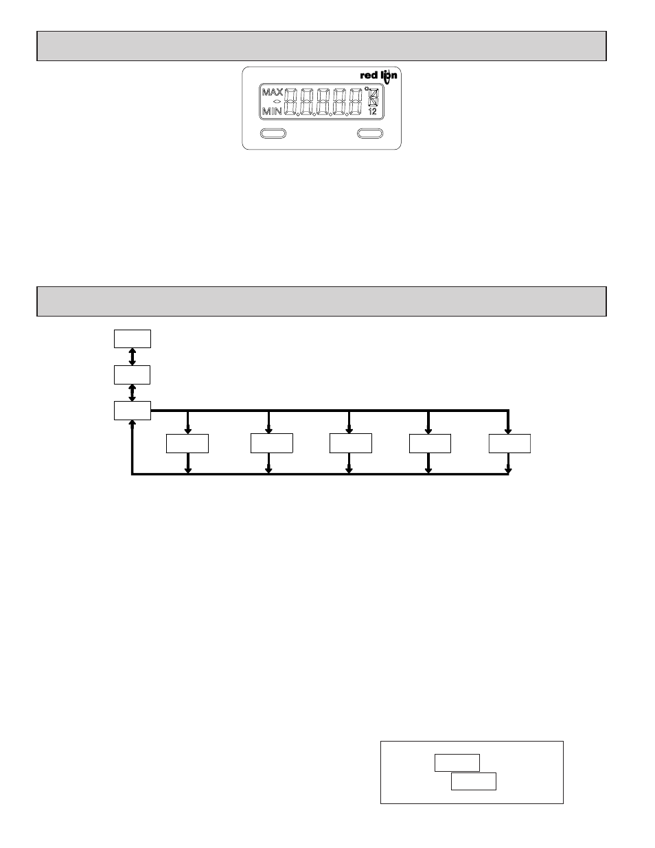
OPERATING MODE DISPLAY DESIGNATORS
MAX
- Maximum display capture value
MIN
- Minimum display capture value
“1” - To the right of the display indicates setpoint 1 output activated.
“2” - To the right of the display indicates setpoint 2 output activated.
Pressing the
SEL
button toggles the meter through the selected displays. If display scroll is enabled, the display will toggle automatically every four seconds between
the enabled display values.
N0
USrIN