Nstalling, Eter, Etting – Red Lion PAXDP User Manual
Page 5: Umpers, Paxdp jumper selection, Linear dc output (paxcdl)
5
LINEAR DC OUTPUT (PAXCDL)
Either a 0(4)-20 mA or 0-10 V retransmitted linear DC output is available
from the analog output plug-in card. The programmable output low and high
scaling can be based on various display values. Reverse slope output is possible
by reversing the scaling point positions.
PAXCDL10 - Retransmitted Analog Output Card
ANALOG OUTPUT CARD
Types: 0 to 20 mA, 4 to 20 mA or 0 to 10 VDC
Isolation To Sensor & User Input Commons: 500 Vrms for 1 min.
Working Voltage: 50 V. Not Isolated from all other commons.
Accuracy: 0.17% of FS (18 to 28°C); 0.4% of FS (0 to 50°C)
Resolution: 1/3500
Compliance: 10 VDC: 10 KΩ load min., 20 mA: 500 Ω load max.
Powered: Self-powered
Step Response: See update rates step response specification
Update time: See ADC Conversion Rate and Update Time parameter
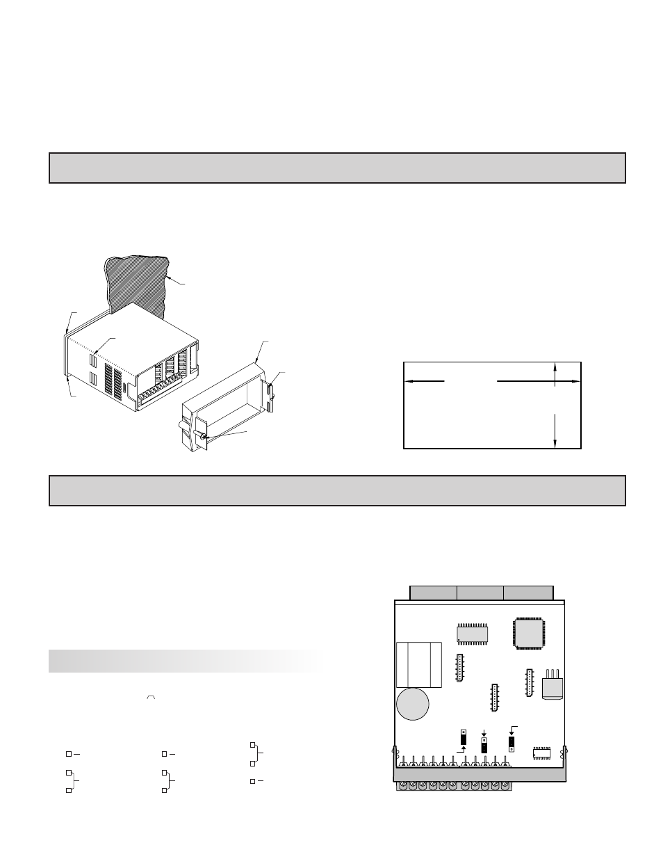
Installation
The PAX meets NEMA 4X/IP65 requirements when properly installed. The
unit is intended to be mounted into an enclosed panel. Prepare the panel cutout to
the dimensions shown. Remove the panel latch from the unit. Slide the panel
gasket over the rear of the unit to the back of the bezel. The unit should be installed
fully assembled. Insert the unit into the panel cutout.
While holding the unit in place, push the panel latch over the rear of the unit
so that the tabs of the panel latch engage in the slots on the case. The panel latch
should be engaged in the farthest forward slot possible. To achieve a proper seal,
tighten the latch screws evenly until the unit is snug in the panel (Torque to
approximately 7 in-lbs [79N-cm]). Do not over-tighten the screws.
Installation Environment
The unit should be installed in a location that does not exceed the maximum
operating temperature and provides good air circulation. Placing the unit near
devices that generate excessive heat should be avoided.
The bezel should be cleaned only with a soft cloth and neutral soap product.
Do NOT use solvents. Continuous exposure to direct sunlight may accelerate the
aging process of the bezel.
Do not use tools of any kind (screwdrivers, pens, pencils, etc.) to operate the
keypad of the unit.
PANEL
LATCHING
SLOTS
BEZEL
PANEL
GASKET
PANEL
LATCH
LATCHING
TABS
PANEL
MOUNTING
SCREWS
-.00
(92 )
-.0
+.8
3.62
+.03
(45 )
1.77
-.0
+.5
-.00
+.02
PANEL CUT-OUT
1.0 i
nsTalling
The
m
eTer
2.0 s
eTTing
The
J
umpers
The meter has three jumpers that must be checked and/or changed prior to
applying power. The following Jumper Selection Figures show an enlargement
of the jumper area.
To access the jumpers, remove the meter base from the case by firmly
squeezing and pulling back on the side rear finger tabs. This should lower the
latch below the case slot (which is located just in front of the finger tabs). It is
recommended to release the latch on one side, then start the other side latch.
Input Jumpers
These jumpers are used to select the proper input types, Voltage (V) or Current
(I). The input type selected in programming must match the jumper setting. See
the Jumper Selection Figures for more details.
User Input Logic Jumper
This jumper selects the logic state of all the user inputs. If the user inputs are
not used, it is not necessary to check or move this jumper.
PAXDP Jumper Selection
SOURCE (SRC)
SINK
USER INPUT
INPUT A
VOLT/CURRENT
VOLT/CURRENT
INPUT B
VOLTAGE (V)
CURRENT (I)
VOLTAGE (V)
CURRENT (I)
JUMPER SELECTIONS
The
indicates factory setting.
REAR TERMINALS
(CURRENT) I
FRONT DISPLAY
INPUT JUMPER LOCATIONS
USER INPUT
JUMPER
LOCATION
(VOLTAGE) V
INPUT A
INPUT B
V
I
Note: In the figures above, the text shown in parenthesis is printed on the
circuit board to help with proper jumper positioning.