4 module 4 - s, Econdary, Unction – Red Lion PAXDP User Manual
Page 15: Arameters
15
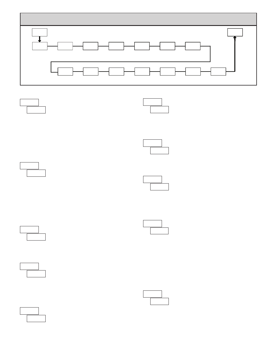
4-SEC
OFS-b
OFS-A
HI-AS
LO-t
dSP-t
PAR
Input A
Offset Value
Input B
Offset Value
Min Capture
Delay Time
Display Update
Rate
HI-t
LO-AS
Min Capture
Assignment
b-LIt
Units Label
Backlight
Max Capture
Delay Time
Max Capture
Assignment
Pro
Calculation
Filter Band
Calculation
Decimal Point
CFunc
Calculation
Filter Setting
C FLt
Calculation
Constant Value
C dP
conSt
Calculation
Rounding
C rnd
C bNd
Calculation
Function
6.4 mOdule 4 - s
eCOndary
f
unCTiOn
p
arameTers
(
)
PARAMETER MENU
INPUT A OFFSET VALUE*
Unless a Zero Display was performed or an offset from Module 1 scaling is
desired for Input A, this parameter can be skipped. The Display Offset Value is
the difference between the Absolute (gross) Display value and the Relative (net)
Display value for the same input level. The meter will automatically update this
Display Offset Value after each Zero Display. The Display Offset Value can be
directly keyed-in to intentionally add or remove display offset. See Relative /
Absolute Display and Zero Display explanations in Module 2.
to
INPUT B OFFSET VALUE*
Unless a Zero Display was performed or an offset from Module 1 scaling is
desired for Input B, this parameter can be skipped. The Display Offset Value is
the difference between the Absolute (gross) Display value and the Relative (net)
Display value for the same input level. The meter will automatically update this
Display Offset Value after each Zero Display. The Display Offset Value can be
directly keyed-in to intentionally add or remove display offset. See Relative /
Absolute Display and Zero Display explanations in Module 2.
to
MAX CAPTURE DELAY TIME
When the Input Display is above the present MAX value for the entered
delay time, the meter will capture that display value as the new MAX reading.
A delay time helps to avoid false captures of sudden short spikes.
to
sec.
MAX CAPTURE ASSIGNMENT
Select the desired parameter that will be assigned to the Max Capture.
MIN CAPTURE ASSIGNMENT
Select the desired parameter that will be assigned to the Min Capture.
MIN CAPTURE DELAY TIME
When the Input Display is below the present MIN value for the entered delay
time, the meter will capture that display value as the new MIN reading. A delay
time helps to avoid false captures of sudden short spikes.
UNITS LABEL BACKLIGHT
The Units Label Kit Accessory contains a sheet of custom unit overlays
which can be installed in to the meter’s bezel display assembly. The backlight
for these custom units is activated by this parameter.
DISPLAY UPDATE RATE
This parameter determines the rate of display update.
to
sec.
updates/sec.
CALCULATION DECIMAL POINT
This parameter determines the decimal point location for the Calculation
Display. For the
,
, and
calculation functions, Input A
“Display Decimal Point”, Input B “Display Decimal Point” and “Calculation
Decimal Point” must all be in the same position.
CALCULATION FUNCTION
This parameter determines the math calculation that will be performed on Input
A and Input B and shown on the calculation display. The above formulas
represent the available calculations;
= Input A relative value,
= Input B
relative value, and
= Calculation Constant Value (
). For the average
between A and B inputs, scale the display (Input A & Input B
x) values in
half and then use C
A
b.
Note:
= add,
-
= subtract,
= division,
()
is displayed in the PAX
as
and the function performs with A divided b then 1 is subtracted and
the result is multiply by c.
*
The decimal point position is dependent on the selection made in the
“Display Decimal Point” parameter.
()