Ommunicating, Raphite, Configuring graphite – Red Lion G15 15" LCD color touch panel User Manual
Page 7: Usb, data transfers from the sd card, Insertion/removal of the sd card, Cables and drivers, Ethernet communications, Rs232 ports, Usb host leds
7
CONFIGURING GRAPHITE
The Graphite is configured using Crimson
®
software. Crimson is available as
a free download from Red Lion’s website. Updates to Crimson for new features
and drivers are posted on the website as they become available. By configuring
the Graphite using the latest version of Crimson, you are assured that your unit
has the most up to date feature set. Crimson
®
software can configure the Graphite
through the RS232 PGM port, USB port, or SD card.
The USB port is connected using a standard USB cable with a Type B
connector. The driver needed to use the USB port will be installed with Crimson.
The RS232 PGM port uses a programming cable made by Red Lion to connect
to the DB9 COM port of your computer. If you choose to make your own cable,
use the “Port Pin Out Diagram” that corresponds to your specific model for
wiring information.
The SD card can be used to program a Graphite by placing a configuration file
and firmware on the SD card. The card is then inserted into the target Graphite
and powered. Refer to the Crimson literature for more information on the proper
names and locations of the files.
USB, DATA TRANSFERS FROM THE SD
CARD
In order to transfer data from the SD card via the USB port, a driver must be
installed on your computer. This driver is installed with Crimson and is located
in the folder C:\Program Files\Red Lion Controls\Crimson 3.0\Device\ after
Crimson is installed. This may have already been accomplished if your Graphite
was configured using the USB port.
Once the driver is installed, connect the Graphite to your PC with a USB
cable, and follow “Mounting the SD” instructions in the Crimson 3 user manual.
USB HOST LEDS
COLOR
STATUS
OFF
Not operational
RED
Error
GREEN
Normal operation
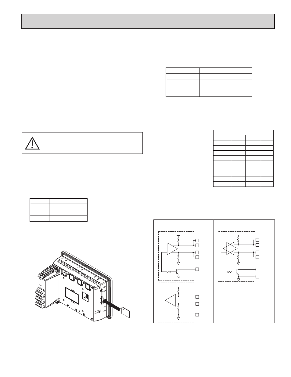
INSERTION/REMOVAL OF THE SD CARD
Insert the SD card into the slot provided with the card oriented as shown. The
card is inserted properly when the end of the card is flush with the Graphite
case. To remove the SD card, push in slightly on the card.
CABLES AND DRIVERS
Red Lion has a wide range of cables and drivers for use with many different
communication types. A list of these drivers and cables along with pin outs is
available from Red Lion’s website. New cables and drivers are added on a
regular basis. If making your own cable, refer to the “Port Pin Outs” that
corresponds to your specific model for wiring information.
ETHERNET COMMUNICATIONS
Ethernet communications can be established at either 10 BASE-T or 100
BASE-TX. The Graphite unit’s RJ45 jack is wired as a NIC (Network Interface
Card). For example, when wiring to a hub or switch use a straight-through cable,
but when connecting to another NIC use a crossover cable.
The Ethernet connector contains two LEDs. A yellow LED in the upper right,
and a green LED in the upper left. The LEDs represent the following statuses:
LED COLOR
DESCRIPTION
YELLOW solid
Link established.
YELLOW flashing
Data being transferred.
GREEN (OFF)
10 BASE-T Communications
GREEN (ON)
100 BASE-TX Communications
On the rear of each unit is a unique 12-digit MAC address and a block for
marking the unit with an IP address. Refer to the Crimson manual and Red
Lion’s website for additional information on Ethernet communications.
RS232 PORTS
The Graphite has two RS232
ports. There is the PGM port and the
COMMS port. Although only one of
these ports can be used for
programming, both ports can be used
for communications with a PLC.
The RS232 ports can be used for
either master or slave protocols with
any Graphite configuration.
RS422/485 COMMS PORT
The Graphite has one RS422/485 port. This port can be configured to act as
either RS422 or RS485.
Note: All Red Lion devices connect A to A and B to B. Refer to www.redlion.net
for additional information.
WARNING - DO NOT CONNECT OR DISCONNECT CABLES
WHILE POWER IS APPLIED UNLESS AREA IS KNOWN TO BE
NON-HAZARDOUS. USB PORT IS FOR SYSTEM SET-UP AND
DIAGNOSTICS AND IS NOT INTENDED FOR PERMANENT
CONNECTION.
Graphite RS232 to a PC
Gxx: RJ12 Name PC: DB9 Name
4
COMM
1
DCD
5
Tx
2
Rx
2
Rx
3
Tx
N/C
4
DTR
3
COMM
5
GND
N/C
6
DSR
1
CTS
7
RTS
6
RTS
8
CTS
N/C
9
RI
TX
5V
8
1
7
2
TxB
TxA
130K
130K
5
TxEN (OC)
RX
130K
5V
130K
RxB
4
RxA
3
COMM
6
TxEN (OC)
TX/RX
130K
5
TxA
2
8
130K
5V
7
1
TxB
6
COMM
RS422/485 4-WIRE
CONNECTIONS
RS485 2-WIRE
CONNECTIONS
7
c
ommunicating
W
ith
the
g
raphite