Perator, Nterface, Nstallation – Red Lion G15 15" LCD color touch panel User Manual
Page 4
44
o
perator
i
nterface
i
nStallation
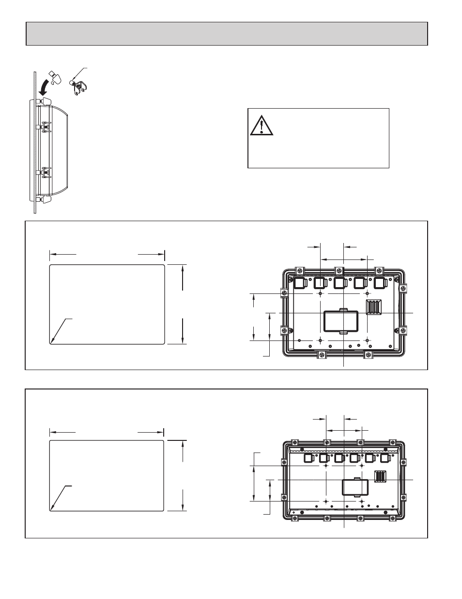
MOUNTING INSTRUCTIONS
This operator interface is primarily designed for
through-panel mounting. Four VESA mount tapped
screw-holes (M4 x 0.7, 5 mm deep) are present on the
rear of the panel to allow for stand or wall mounting.
Care should be taken to remove any loose material from
the mounting cut-out to prevent that material from falling
into the operator interface during installation. A gasket is
provided to enable sealing to NEMA 4X/IP66
specification. Install the mounting clips provided and
tighten to 6.0 pound-force inch (96 ounce-force inch)
evenly for uniform gasket compression.
FOOT MAY BE REMOVED
FOR THICKER PANEL
INSTALLATIONS
ALL NONINCENDIVE CIRCUITS MUST BE
WIRED USING DIVISION 2 WIRING
METHODS AS SPECIFIED IN ARTICLE 501-4
(b), 502-4 (b), AND 503-3 (b) OF THE
NATIONAL ELECTRICAL CODE, NFPA 70
FOR INSTALLATION WITHIN THE UNITED
STATES, OR AS SPECIFIED IN SECTION
19-152 OF CANADIAN ELECTRICAL CODE
FOR INSTALLATION IN CANADA.
4.869
(123.7)
7.060 (179.3)
4X R.10 (2.5)
MAX.
All tolerances ±.059" (±1.5 mm)
PANEL CUT-OUT
2.95 (75)
1.48 (37.5)
2.95
(75)
1.73
(44)
VESA MOUNT (MIS-D 75) DIMENSIONS
G07
5.832
(148.1)
9.423 (239.3)
4X R.10 (2.5)
MAX.
All tolerances ±.059" (±1.5 mm)
PANEL CUT-OUT
1.77
(45)
2.95
(75)
2.95 (75)
1.48 (37.5)
VESA MOUNT (MIS-D 75) DIMENSIONS
G09