Advanced | premium calibration tools – Monoprice 9497 Disney World of Wonder User Manual
Page 14
24
25
locate the display controls affecting “hue” or “tint.” Using the blue
filter, observe the main color bar samples of cyan and magenta.
Directly beneath those are reversed samples of magenta and cyan.
Adjust the hue or tint control to balance the levels of the main color
bars with the samples on the reverse strip.
The hue or tint is now properly adjusted.
Please keep in mind the chroma level will
interact with the hue control, one placing
the other slightly out of balance. Go back
and forth between adjusting the color
and hue a few times until both settings
are optimal (figure 27).
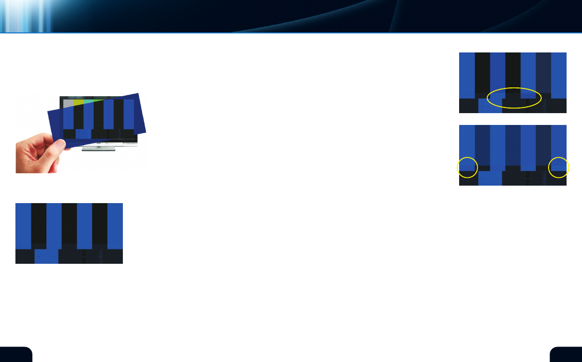
The color bar pattern on the left is
properly adjusted (figure 27). notice that all visible bars are the
same shade when seen through the blue filter. It is likely that your
television will either match this condition or will
be very close right out of the box. You may test
for proper adjustment by moving the controls
slightly to observe the changes. To the right are
examples of what you will see when the controls
are misadjusted. Adjust the controls to match
the example shown here on the left.
The most critical adjustment is the “hue” or “tint”
control. This adjustment will have a dramatic impact on flesh tones
if misadjusted. While looking through the blue filter, adjust the
control in either direction until you see the two center bars change
shade. The narrow strip of reverse color bars under the main bars
will assist in precise adjustment of hue or tint. Adjust the control
until the transition between the main center bars and the reverse
bars below disappears. The next example on the right shows what
hue or tint
adjustMent
color
adjustMents
(figure 26)
(figure 27)*
(figure 28)
the hue looks like when misadjusted (figure 28).
The “chroma” or “color” control will interact
slightly with the “hue” or “tint” control. While
looking through the blue filter, adjust the
control until the shades of the far left and far
right main color bars diverge from the narrow
strip of reverse color bars below (figure 29).
The adjustment is correct when the transition
between the main bars and the reverse bars on
the far left and right sides disappears as in the
reference image (figure 27). You may need to
alternate between the “color” and “hue” control
to achieve perfection. The example on the right
shows what chroma or color looks like when
misadjusted. This concludes the use of the blue
filter gel.
The bottom quarter of the color bar pattern has a full width solid
bar of ideal digital black containing two test signal areas. On the
next page is a strip (figure 30) containing a box of ideal digital
white along with vertical strips showing three steps slightly lighter
and darker than ideal white. On the right side of the strip is a similar
arrangement with ideal digital black as the background along with
vertical strips slightly lighter and darker than ideal black. These
are “PlUGE” signals, which stands for “Picture line Up GEnerator.”
The PlUGE signal aids the adjustment of proper black and white
displayed by a monitor. The PlUGE signals, which may be difficult
to spot, are marked with short horizontal grey bars.
Any monitor has a maximum range of light output for both black
and white, called “contrast ratio.” The contrast control adjusts the
luMinance
adjustMents
(figure 29)
advanced | PREmIUm cAlIBRATIOn TOOlS
Monitor selection
*Digital Reference Standard