Convergence test, Advanced | premium calibration tools – Monoprice 9497 Disney World of Wonder User Manual
Page 12
20
21
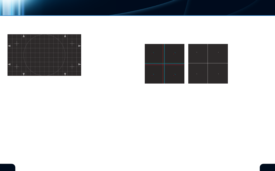
white grid without color fringes. Below are examples of incorrect
alignment and correct final alignment (figure 23).
Occasionally, several projectors are “stacked” together to achieve
a higher screen brightness than is otherwise available. Use the
focus chart found elsewhere on this disc to set up the individual
projectors first. Use this test pattern to perform the aiming and
sizing alignments of all projectors together. Test your alignment
with live images to confirm successful registration.
On cRT based systems, you may encounter adjustments useful for
correcting geometric distortions other than sizing. This crosshatch
chart and others containing uniform geometric shapes will be useful
for making these adjustments. The following illustrations show some
of these deficiencies. Adjust the appropriate controls to achieve
uniform squares in the crosshatch and a round circle in the center.
note that three gun cRT systems may have these controls for each
gun, which requires patience for successful adjustment (figure 24,
see next page).
(figure 23)*
CONVERGENCE tEst
crosshatch display
This test pattern (figure 22)
is a regular grid of squares.
There are 16 squares horizon-
tally and 9 squares vertically,
corresponding to the aspect
ratio of current HDTV equip-
ment. This pattern is most
useful for direct view cRT
monitors or projection systems
that require the registration of
multiple image sources.
The mechanics of a cRT dictate a separate source for red, green
and blue image elements. These three color sources must be
“registered” so they fit together on the screen. many modern cRTs
have no controls for registration as the alignment is part of the
device’s construction. However, some systems have adjustments
to precisely align the individual “guns” so they coincide on the
display. Do not attempt to adjust registration yourself if it involves
opening the monitor as dangerous high voltage is present inside
the cabinet. If external controls do exist, be advised that this
adjustment is reserved for the most skillful and patient of people.
Use this test pattern to align a projection system using three
individual optical color sources. Typically, the registration controls
are easily accessible in these systems as they need touch-up after
moving the equipment. Set the green channel to be correct in
sizing, geometry, focus etc. Then, adjust the red and blue controls
to match the green, so the entire test chart appears as a uniform
(figure 22)*
direct
view crts
three Gun
projectors
Multiple
projectors
GeoMetric
distortions
misaligned
Aligned
advanced | PREmIUm cAlIBRATIOn TOOlS
Monitor selection
*Digital Reference Standard
*Digital Reference Standard