Parts, Installation – JKS OGS159 User Manual
Page 2
JKS OGS159
JKS Adjustable Track Bar Installation
2 Page
Parts
Description
QTY
A
Male Threaded (Chassis) End
1
B
Female Threaded (Axle) End
1
C
1” NF Jam Nut
1
D
Rubber Bushing
2
Installation
1. REMOVE REAR TRACK BAR
Raise and support the vehicle chassis with jack
stands positioned in front of the rear lower suspen-
sion arm brackets.
Raise and support the rear axle housing with
a hydraulic jack to relieve any tension from the
mounting bolts.
Remove the rear track bar mounting hardware
from the axle and chassis brackets per the fac-
tory service manual instructions for your vehicle.
Retain original hardware.
Remove original track bar from vehicle.
2. MOUNT ADJUSTABLE TRACKBAR TO
AXLE BRACKET
Apply anti-seize lubricant to bolt threads of original
track bar mounting hardware.
Insert Axle End (B) of the adjustable trackbar into
the axle bracket with the differential clearance
bend towards the rear
Note: On RHD vehicles the pre-installed sticker is
upside down. A new one is provided to place over the
existing sticker.
Loosely install the original mounting hardware.
3. CENTER REAR AXLE HOUSING
Remove jack stands and lower vehicle to ground.
HINT: Vehicle must be at normal ride height, on
level ground, with the suspension supporting the
full vehicle weight.
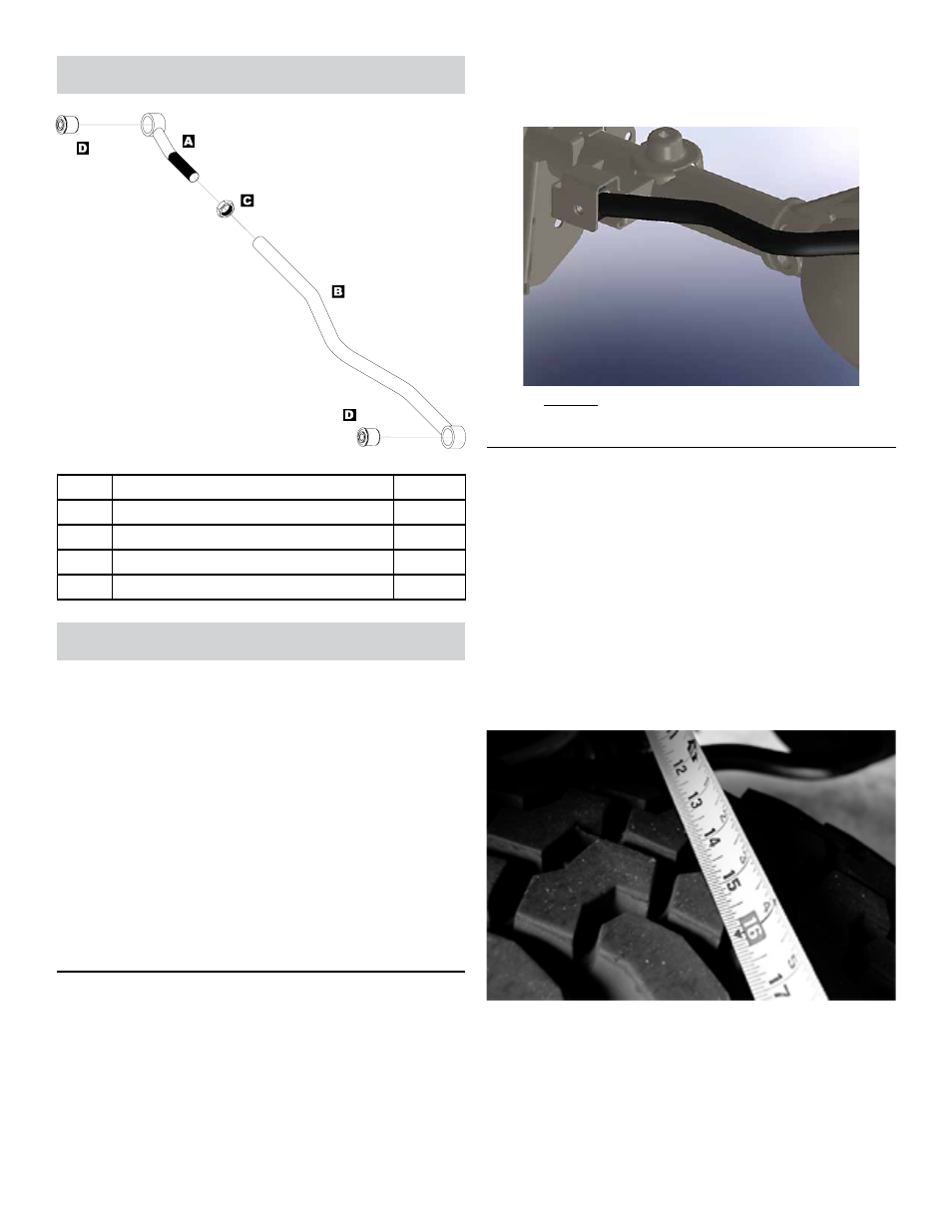
Determine if the axle housing is centered by
measuring the distance between the tire and
chassis, using the exact same points on each
side of the vehicle to ensure accuracy.
HINT: For
example, measure from the edge of a tire tread lug
to the outboard side of the chassis, then repeat the
measurement on the other side of vehicle using
exact same points.
If the two measurements are equal, the axle is
centered. If the measurements vary, divide the dif-
ference in half to determine the amount of adjust-
ment required.
HINT: If the axle housing is not
centered, the chassis can be laterally shifted using
either of the following methods.