Installation, Operation, Troubleshooting – JKS 9800 User Manual
Page 2: Maintenance
JKS9800
JKSTelescoping Trackbar Installation
2 Page
Installation
1. REMOVE ORIGINAL EQUIPMENT (OE)
FRONT TRACK BAR
Remove front track bar and mounting hardware –
including U-bracket from chassis – according to the
factory service manual instructions for your vehicle.
Also remove any aftermarket track bar relocation
or riser bracket from axle, if installed. Such parts
are commonly supplied with suspension lift kits.
IMPORTANT: It will be necessary for the OE pitman
arm to be installed on the steering box if aftermarket
relocation/riser bracket is removed from the axle.
However, if special circumstances require the reloca-
tion/riser bracket to be retained, it will also be neces-
sary to retain the drop pitman arm.
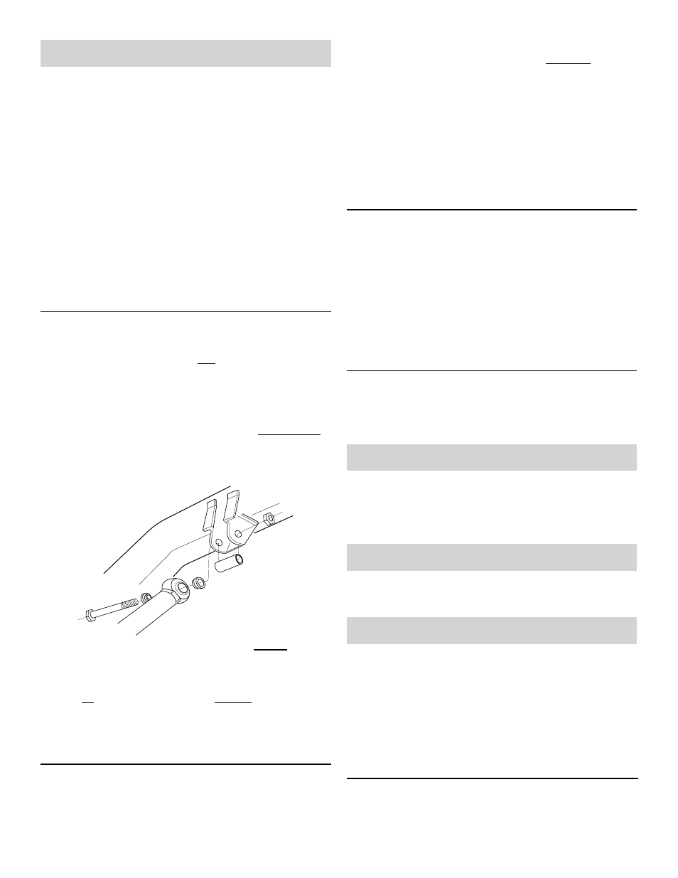
2. MOUNT TELESCOPING TRACKBAR TO
CHASSIS BRACKET
Insert 1.85” Spacer (N) into chassis rail bracket
where the OE track bar originally mounted. HINT:
The 1.85” Spacer (marked with an “X”) prevents
the OE bracket from collapsing.
Insert a 5/16” (wide) Shoulder Spacer (O) into
each side of the Rod End (D) at the Chassis End
(A) of Telescoping Trackbar.
HINT: The Shoulder
Spacers must “sandwich” the Rod End to allow full
flexibility of the joint when installed.
Mount Chassis End (A) of trackbar behind the
chassis rail bracket and secure with the 1/2” x
4-1/2” Bolt (P) and 1/2” Ovalok Nut (C). HINT:
When installed correctly, Grease Zerk (L) will point
up and JKS decal will face forward.
Tighten 1/2” x 4-1/2” Bolt (P) to 75 ft-lb. using a
torque wrench.
3. MOUNT TELESCOPING TRACKBAR TO
AXLE BRACKET
Using a 1/2” drill bit, enlarge the hole on the axle
where the OE track bar originally mounted.
Insert a 1/8” (narrow) Shoulder Spacer (M) into
each side of Rod End (D) at the Axle End (B) of
Telescoping Trackbar.
HINT: Shoulder Spacers
must “sandwich” the Rod End to allow full flexibility
of the joint when installed.
Mount Axle End (A) of trackbar to axle bracket and
secure with a 1/2” x 3” Bolt (G) and 1/2” Ovalok
Nut (C).
Tighten 1/2” x 3” Bolt (G) to 75 ft-lb. using a torque
wrench.
4. TIGHTEN TELESCOPING TRACKBAR
With the vehicle on a level surface, tighten the
Clamp (J) using a 9/16” wrench.
Tighten the 3/4” Jam Nuts (E) located at each end of
the trackbar, but DO NOT thread out Rod Ends (D).
IMPORTANT: Rod Ends have been properly installed
from the factory. Avoid unthreading Rod Ends prior to
installation, as this may sacrifice strength
5. LUBRICATE TELESCOPING TRACKBAR
Lubricate the Grease Zerk (L) located on the
Clamp (J) of Telescoping Trackbar using common
wheel bearing grease or equivalent.
Operation
Telescoping Trackbar should remain in the “locked”
position when vehicle is operated on public roads. Once
off-road, the trackbar can be “unlocked” by loosening the
Clamp (J) using a pair of 9/16” wrenches.
Troubleshooting
If slippage occurs on Chassis End of Telescoping Trackbar,
weld the 1.85” OE Bracket Spacer (N) in place.
Maintenance
Telescoping Trackbar is factory lubricated, but should be
greased regularly as part of vehicle maintenance schedule.
Regular cleaning with pressurized water is recommended
to maximize ease of operation and reliability. Always lubri-
cate afterwards to evacuate any moisture.
Check torque specifications regularly.
©2013 JKS Manufacturing, Inc & Aftermarketing, LLC
Revision Date 10/31/2013