JKS 7150 User Manual
Page 2
JKS7150
JKS Adjustable Control Arm Installation
2 Page
Remove the electrical clip from the suspension
arm clevis bracket if equipped.
Remove the upper suspension arm nut and bolt
from the axle housing bracket. Retain the original
mounting hardware.
Remove the nut and bolt from the chassis rail
bracket. Retain the original mounting hardware.
IMPORTANT: To remove the passenger side bolt from
the chassis, it will be necessary to raise the engine
according to the following instructions.
Â
Position a second hydraulic jack beneath
mounting flange of engine oil pan. Support
engine using a suitable block of wood (2x4
or larger) to distribute weight across oil pan
bolts.
DO NOT attempt to lift the engine by
engine oil pan.
Â
Carefully raise the hydraulic jack just enough
to remove the weight of the engine from the
engine mounts.
Â
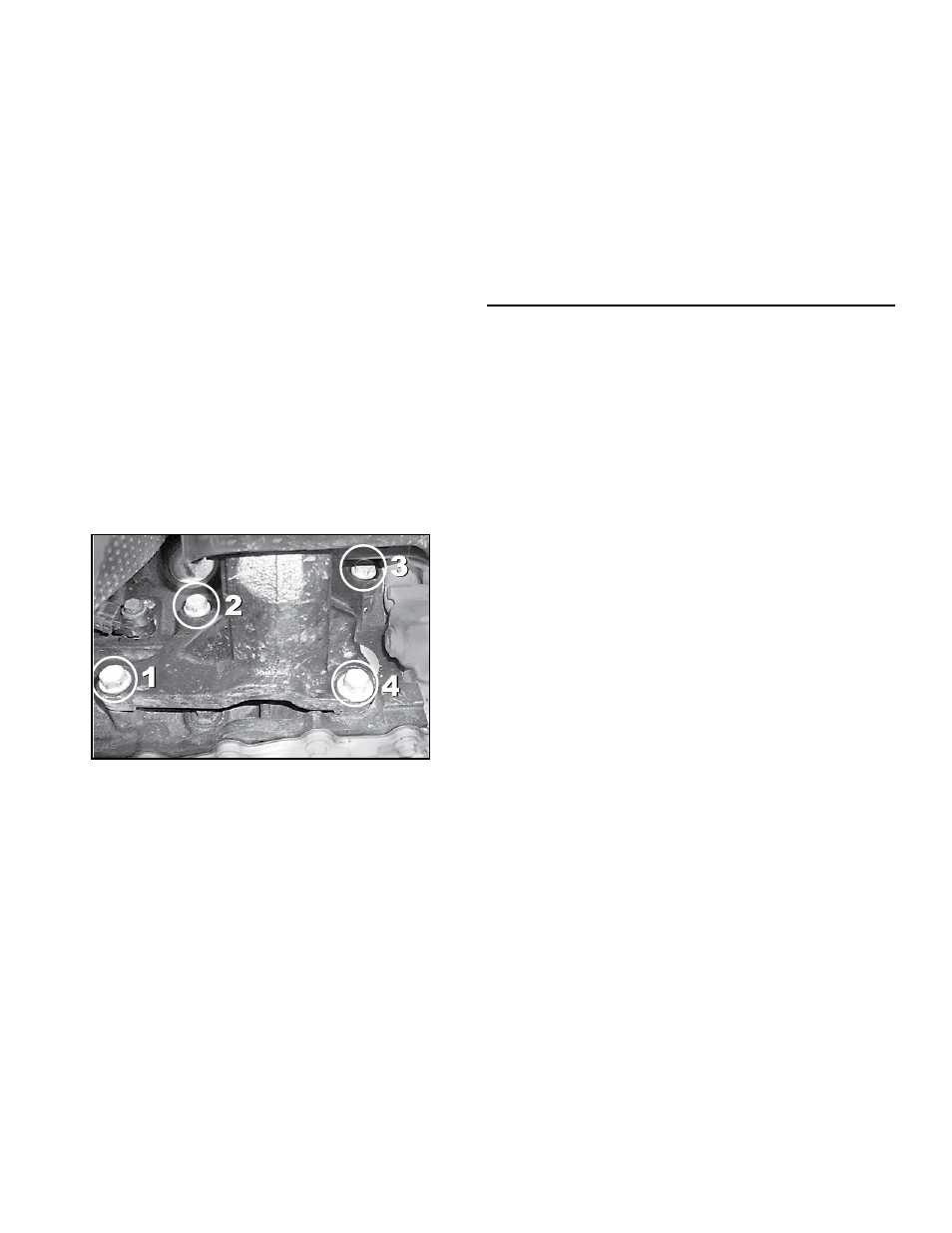
Locate the passenger side engine mount
bracket and remove the four (4) bolts that
secure it to the engine block.
Â
Slowly raise the hydraulic jack approximately
1-2 inches until the passenger side control
arm bolt clears the interfering exhaust pipe.
Â
Continue following instructions with engine in
raised position and begin Control Arm instal-
lation with passenger side first.
Remove the original upper suspension arm from
the vehicle.
2. SET CONTROL ARM LENGTH
Adjustable Control Arms are fully collapsed when supplied
from JKS and must be adjusted to the desired lengths
before installation.
The working length of each upper Control Arm can be
increased (up to 3.625” longer), decreased (up to 0.5”
shorter), or exactly the same as the OE suspension arm.
Determine ideal Control Arm length for your ap-
plication by considering factors such as:
Â
Length of OE suspension arm
Â
Tire Clearance
Â
Pinion Angle / Caster
Rotate adjustable end of Control Arm until the
desired length is achieved.
Adjust corresponding Control Arm to exact same
length.
3. INSTALL CONTROL ARM
Apply anti-seize lubricant to bolt threads of original
mounting hardware.
Mount the rotating (GOLD) end of Adjustable
Control Arm to the chassis rail bracket with the
greaseable fitting facing up.
Install the original mounting bolt from inboard side.
Bolt threads should point outboard.
IMPORTANT: Passenger side bolt must be installed
with engine in the raised position to provide sufficient
clearance around exhaust pipe.
Â
With the Control Arm positioned in the chas-
sis rail bracket, insert the original bolt into the
mounting hole.
Â
Carefully lower the hydraulic jack until the
passenger side engine mount support bracket
is realigned with the engine block.
Â
Install the four (4) original bolts into the cor-
responding mounting holes and tighten to 45
ft-lbs. using a torque wrench.
Â
Lower the hydraulic jack and remove block of
wood from beneath engine oil pan.
Install the original mounting nut and finger tighten.
DO NOT torque mounting hardware until instruct-
ed.
Mount the non-rotating (BLACK) end of Adjustable
Control Arm to the axle housing bracket.
Install the original mounting bolt from inboard side.
Bolt threads should point outboard.
Install the original mounting nut and finger tighten.
DO NOT torque mounting hardware until instruct-
ed.
HINT: If mounting bolt is difficult to install due to misalign-
ment of Control Arm bushing with mounting bracket, either
(1) adjust height of axle housing with hydraulic jack, (2)
move axle housing into position with a heavy-duty ratchet
strap, or (3) temporarily disconnect track bar until mount-
ing holes align.