X” – 1/4 ” = ride height, Do not exceed – JKS 2700 User Manual
Page 7
JKS AC
OS Pro™ Installation
PN 2700
Page 7 of 8
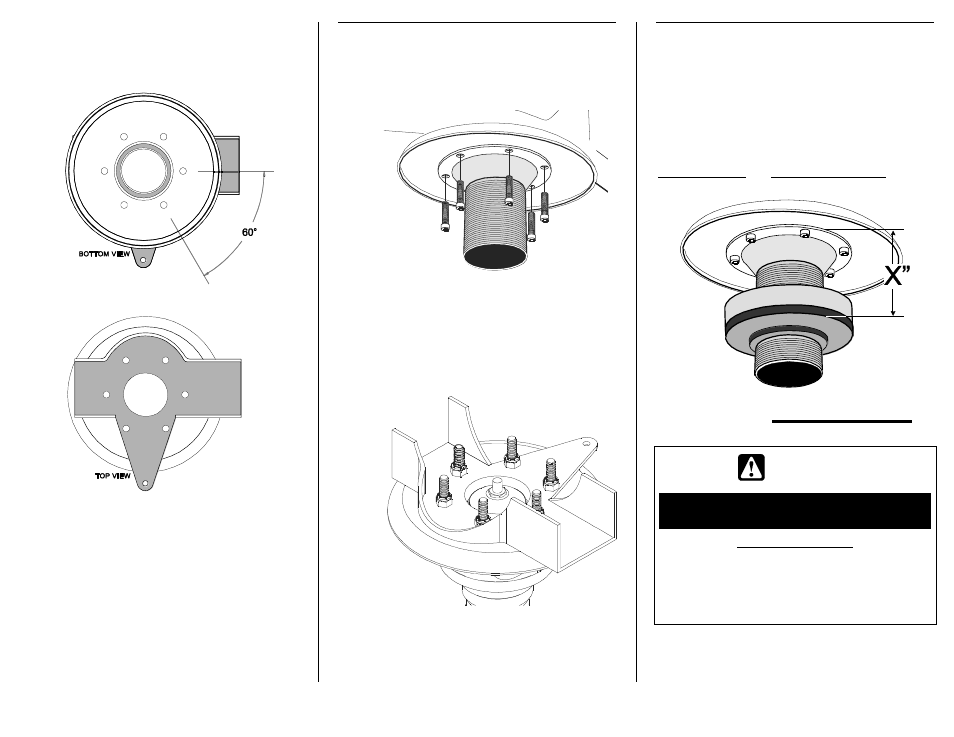
Using the Main Body (B) as a template,
accurately mark all six hole locations on the
upper spring mount using a transfer punch or
equivalent. HINT: Hole locations should align
with spring mount bracket as indicated below.
Using a 1/4” bit, drill a pilot hole at each hole
location. Enlarge each hole with a 3/8” drill bit.
Paint any exposed metal on the upper spring
mount to prevent corrosion.
5. INSTALL MAIN BODY OF ACOS
PRO
ON UPPER SPRING MOUNT
Position the Main Body (B) against the bottom
of the upper spring mount and align the
mounting holes.
Insert a 5/16” x 1-1/4” Cap Bolt (C) through
each hole. Loosely secur
e with a 5/16” Nylock
Nut (D) from above the spring mount.
HINT: It is not necessary to install the supplied
Reinforcement Ring (A) on rear applications.
Once all six bolts have been installed, tighten
the 5/16” Nylock Nuts (D) to 40 ft-lbs. using a
torque wrench.
6. SET ADJUSTER RING FOR
DESIRED RIDE HEIGHT
Apply spray lubricant to threads of Main Body
(B). Install Adjuster Ring (E) by threading
clockwise onto Main Body (B).
Slide Isolator Pad (G) onto Main Body until flush
with Adjuster Ring (E).
IMPORTANT: Vehicle ride height is determined
by measuring the distance between the
top of Main Body and bottom of Isolator Pad,
and then subtracting 1
/4” (0.25 in.).
X
” – 1/4” = RIDE HEIGHT *
* Represents increase in ride height over OE suspension
WARNING
DO NOT EXCEED
MAXIMUM RANGE OF ADJUSTMENT
ADJUSTMENT RANGE
MINIMUM: 1-3/4
” (1.750 in.)
MAXIMUM: 3-5/8
” (3.625 in.) **
** MAXIMUM: 2-
1/8” (2.125 in.) if Main Body
was shortened 1-
1/2” in step 3
Rotate Adjuster Ring (E) to desired position and
tighten the recessed
3/8” x 1-1/4” Cap Bolt (F)
to lock in place.